Information autom. advance mechanism
BOSCH
9 420 617 209
9420617209
ZEXEL
105612-2100
1056122100

Rating:
Scheme ###:
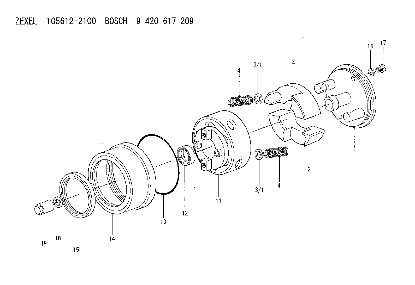
| 1. | [1] | 156133-1720 | FLYWEIGHT ASSEMBLY |
| 2. | [2] | 156108-5900 | FLYWEIGHT |
| 2. | [2] | 156108-5900 | FLYWEIGHT |
| 3/1. | [0] | 029310-9010 | SHIM D19.6&9T0.5 |
| 3/1. | [0] | 029310-9020 | SHIM D19.6&9T1 |
| 3/1. | [0] | 029310-9030 | SHIM D19.6&9T0.1 |
| 3/1. | [0] | 029310-9040 | SHIM D19.6&9T0.2 |
| 3/1. | [0] | 029310-9050 | PLAIN WASHER D19.6&9T1.5 |
| 3/1. | [0] | 139409-0000 | SHIM D19.6&9.0T0.15 |
| 3/1. | [0] | 139409-0000 | SHIM D19.6&9.0T0.15 |
| 4. | [2] | 156125-1400 | COMPRESSION SPRING |
| 4. | [2] | 156125-1400 | COMPRESSION SPRING |
| 4B. | [2] | 156125-1500 | COMPRESSION SPRING |
| 4C. | [2] | 156125-1600 | COMPRESSION SPRING |
| 4D. | [2] | 156125-1700 | COMPRESSION SPRING |
| 4E. | [2] | 156125-1800 | COMPRESSION SPRING |
| 11. | [1] | 156131-0320 | FLANGE BUSHING |
| 12. | [1] | 029622-8010 | PACKING RING |
| 13. | [1] | 156117-0100 | O-RING |
| 14. | [1] | 156114-0700 | CASE |
| 15. | [1] | 156116-0720 | PACKING RING |
| 16. | [2] | 026508-1240 | GASKET D11.9&8.2T1 |
| 17. | [2] | 156115-0100 | CAPSULE |
| 18. | [1] | 014111-2420 | LOCKING WASHER |
| 19. | [1] | 131325-0200 | UNION NUT |
Include in #1:
101681-9570
as AUTOM. ADVANCE MECHANIS
Cross reference number
Zexel num
Bosch num
Firm num
Name
105612-2100
9 420 617 209
AUTOM. ADVANCE MECHANISM
* K
* K
Information:
Liner Projection Check
(1) 1P2402 Gauge Body. (2) 1P2403 Dial Indicator.3. Use body (1) and dial indicator (2) assembly to measure the cylinder liner (flange) projection in four locations around the liner. Do not measure liner projection from the flame ring (if equipped). Projection must be 0.10 mm (.004 in) above to 0.10 mm (.004 in) below the cylinder block face. The four measurements should not vary more than 0.03 mm (.001 in). The average projection between adjacent cylinders must not vary more than 0.03 mm (.001 in)Connecting Rods And Pistons
1. On T4.236 Engines, install the piston cooling jets and tighten the banjo bolt to 25 N m (20 lb ft). Adjust the piston cooling jets if necessary. See Piston Cooling Jet Position Check (T4.236 Engines) in Testing And Adjusting.2. Put a liberal amount of clean engine oil on the crankshaft journals, main bearings and thrust washers. Put the upper half of the main bearings and the crankshaft in position in the cylinder block.3. Slide the upper thrust washer halves into the recesses provided on either side of the center main bearing housing.4. Install the lower half of the main bearings into the main bearing caps. Install the main bearing caps to their respective positions. Position the lower thrust washer halves on either side of the center main bearing cap.5. The main bearing caps are numbered 1 through 5, beginning at the front of the block. Each cap is also marked with a serial number which is also stamped on the cylinder block bottom face. They all should read the same way.6. Install and tighten the main bearing bolts and tighten to a torque of 247 N m (180 lb ft).Use the 1Y7426 Piston Ring Compressor to remove or install piston rings.7. Put a liberal amount of clean engine oil in the bore of each cylinder and on the pistons before they are installed.8. Install the piston and connecting rod assemblies using the piston ring compressor as a guide. Be sure the piston and rod number are the same as for the cylinder bore each is installed in. The rod identification number must be opposite the camshaft. The word "Front" or arrow marked on the piston crown must be toward the front of the engine. If the piston crown is not marked, put the offset (narrowest distance between hole and edge of piston) of the piston toward the fuel injection pump side of the block.The connecting rod bearings must fit tightly in the bore of the rod. If bearing joints or backs are worn (fretted), check for bore size as this is an indication of wear because of looseness. Install the bearing cap with the numbers on the same side of the rod and cap.9. Install the connecting rod bolts so the flat on the bolt head is against the shoulder of the rod. Install new rod nuts. Tighten rod nuts to the torque that follows: Cadmium plated nuts silver color) ... 100 N m (75 lb ft)Phosphated nuts
Have questions with 105612-2100?
Group cross 105612-2100 ZEXEL
105612-2100
9 420 617 209
AUTOM. ADVANCE MECHANISM