Information autom. advance mechanism
BOSCH
9 420 616 355
9420616355
ZEXEL
105612-1670
1056121670
ISUZU
1157401190
1157401190
Rating:
Scheme ###:
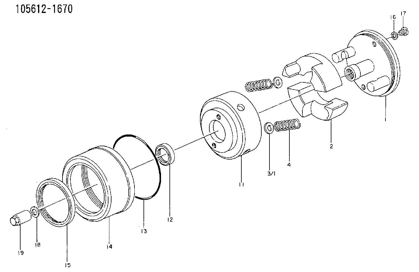
| 1. | [1] | 156133-0420 | FLYWEIGHT ASSEMBLY |
| 2. | [2] | 156108-6100 | FLYWEIGHT |
| 3/1. | [0] | 029310-9010 | SHIM D19.6&9T0.5 |
| 3/1. | [0] | 029310-9020 | SHIM D19.6&9T1 |
| 3/1. | [0] | 029310-9030 | SHIM D19.6&9T0.1 |
| 3/1. | [0] | 029310-9040 | SHIM D19.6&9T0.2 |
| 3/1. | [0] | 029310-9050 | PLAIN WASHER D19.6&9T1.5 |
| 3/1. | [0] | 139409-0000 | SHIM D19.6&9.0T0.15 |
| 4. | [2] | 156124-3100 | COMPRESSION SPRING |
| 11. | [1] | 156130-6820 | FLANGE BUSHING |
| 12. | [1] | 029622-8010 | PACKING RING |
| 13. | [1] | 156117-0100 | O-RING |
| 14. | [1] | 156114-1300 | CASE |
| 15. | [1] | 156116-1020 | PACKING RING |
| 16. | [2] | 026508-1240 | GASKET D11.9&8.2T1 |
| 17. | [2] | 156115-0100 | CAPSULE |
| 18. | [1] | 014111-2420 | LOCKING WASHER |
| 19. | [1] | 131325-0200 | UNION NUT |
Include in #1:
101601-4940
as AUTOM. ADVANCE MECHANIS
Cross reference number
Zexel num
Bosch num
Firm num
Name
105612-1670
9 420 616 355
1157401190 ISUZU
AUTOM. ADVANCE MECHANISM
* K 14KC TIMER SA TIMER
* K 14KC TIMER SA TIMER
Information:
3306 New Scroll Fuel System (NSFS) Hydraulic Actuator
The variable power actuator is mounted to the rear of the governor housing, where the shutoff solenoid is normally mounted. The actuator rod may be in one of two positions -- extended or retracted. The extended position limits the fuel rack travel to the lower power fuel setting. The retracted position allows the fuel rack to travel to the higher power fuel setting. By limiting the travel of the fuel rack, the fuel being injected into the engine is controlled. Fuel being injected into the engine determines the output power of the engine. The position of the actuator rod is determined by the gear engaged in the transmission of the applicable vehicle.High Power Range
Typical Variable Power Arrangement
1. Manifold. 2. Solenoid control valve. 3. Variable power actuator. 4. Governor control lever. 5. Transmission. 6. Switch.An electric switch (6) is mounted in the transmission (5). The transmission (5) is shifted into a gear where the higher power range is allowed. A transmission interlock pin causes the normally open switch (6) to close. When switch (6) is closed, it energizes solenoid control valve (2). The energized solenoid control valve (2) allows engine lube oil (under normal engine lube oil pressure) to flow through manifold (1) and into actuator (3).
Governor And Actuator
3. Actuator. 7. Oil inlet/outlet port. 11. Governor servo valve. 12. Lever. 13. Governor control shaft. 14. Actuator rod.The engine oil coming in port (7) compresses spring (15) and moves actuator rod (14) to the RETRACTED position. The RETRACTED actuator rod (14) allows the fuel rack more travel in the FUEL ON direction by a mechanical linkage through the governor servo valve (11) and lever (12). The fuel rack travel is now limited by the fuel setting screw.The actuator rod (14) will remain in the RETRACTED position as long as solenoid control valve (2) is energized. A light on the operator's console indicates when the engine is operating in the higher power range.
Governor And Variable Power Actuator (Retracted Position7. Oil inlet/outlet port.8. Washered adjusting
Have questions with 105612-1670?
Group cross 105612-1670 ZEXEL
Isuzu
Isuzu
105612-1670
9 420 616 355
1157401190
AUTOM. ADVANCE MECHANISM