Information autom. advance mechanism
BOSCH
9 420 615 094
9420615094
ZEXEL
105612-0670
1056120670
MITSUBISHI
3126110302
3126110302

Rating:
Scheme ###:
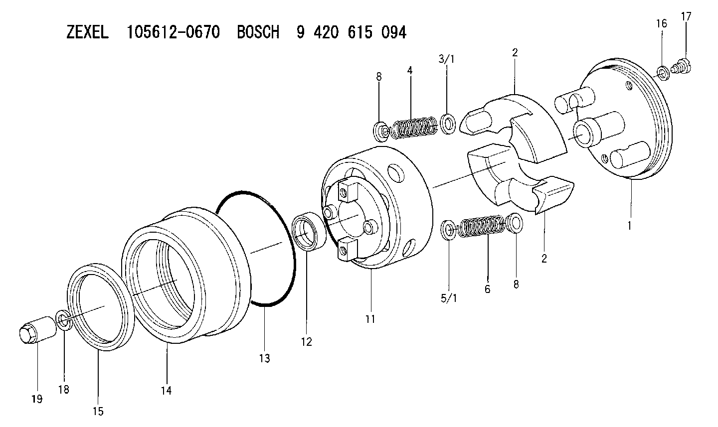
| 1. | [1] | 156132-1620 | FLYWEIGHT ASSEMBLY |
| 2. | [2] | 156108-3700 | FLYWEIGHT |
| 2. | [2] | 156108-3700 | FLYWEIGHT |
| 3/1. | [0] | 029310-9010 | SHIM D19.6&9T0.5 |
| 3/1. | [0] | 029310-9020 | SHIM D19.6&9T1 |
| 3/1. | [0] | 029310-9030 | SHIM D19.6&9T0.1 |
| 3/1. | [0] | 029310-9040 | SHIM D19.6&9T0.2 |
| 3/1. | [0] | 029310-9050 | PLAIN WASHER D19.6&9T1.5 |
| 3/1. | [0] | 139409-0000 | SHIM D19.6&9.0T0.15 |
| 4. | [2] | 156104-5400 | COMPRESSION SPRING |
| 5/1. | [0] | 029310-6010 | SHIM D12.6&6.6T0.30 |
| 5/1. | [0] | 029310-6020 | SHIM D12.6&6.6T0.50 |
| 5/1. | [0] | 029310-6340 | SHIM D12.6&6.6T1.0 |
| 5/1. | [0] | 029310-6350 | SHIM D12.6&6.6T1.5 |
| 6. | [2] | 156106-0900 | COMPRESSION SPRING |
| 8. | [2] | 156107-0800 | SLOTTED WASHER |
| 8. | [2] | 156107-0800 | SLOTTED WASHER |
| 11. | [1] | 156101-7920 | FLANGE BUSHING |
| 12. | [1] | 029622-8010 | PACKING RING |
| 13. | [1] | 156117-0100 | O-RING |
| 14. | [1] | 156114-0700 | CASE |
| 15. | [1] | 156116-0720 | PACKING RING |
| 16. | [2] | 026508-1240 | GASKET D11.9&8.2T1 |
| 17. | [2] | 156115-0100 | CAPSULE |
| 18. | [1] | 014111-2420 | LOCKING WASHER |
| 19. | [1] | 131325-0200 | UNION NUT |
Include in #1:
101891-6880
as AUTOM. ADVANCE MECHANIS
Cross reference number
Zexel num
Bosch num
Firm num
Name
105612-0670
3126110302 MITSUBISHI
AUTOM. ADVANCE MECHANISM
K 14KC AUTOMATIC TIMER TIMER SA TIMER
K 14KC AUTOMATIC TIMER TIMER SA TIMER
Information:
1. Remove the fuel injection lines. It is not necessary to remove the fuel transfer pump, the fuel injection pump housing and governor to remove the fuel injection pumps. 2. Remove cover (1). 3. Move the rack until tool (A) can be installed to hold the rack in the center position. The rack must be in the center position to remove the fuel injection pumps.4. Use tool (B) to remove bushing (2). 5. Install tool (C) on the bonnet and remove the fuel injection pump. 6. Remove spacer (3) from the fuel injection pump housing. Spacers (3) are the same thickness for each fuel injection pump so they can be mixed. The fuel injection pump plungers and barrels are sets and can not be mixed.Install Fuel Injection Pumps
1. Install spacer (1) in the fuel injection pump housing. 2. Move the rack until tool (A) can be installed to hold the rack in the center position. The rack must be in the center position to install the fuel injection pumps.3. Turn the camshaft until the lobe of the camshaft is down for the pump to be installed. 4. Install tool (B) on the bonnet of the fuel injection pump. Put clean oil on O-ring seal (4) and install the O-ring seal and bushing (5) over tool (B) as shown. 5. Install the fuel injection pump in the pump housing with saw cut (slot) (3) in the gear in alignment with small pin (2) in the lifter assembly and groove (7) in the barrel in alignment with large pin (6) in the pump housing.6. Push down on tool (B) and tighten bushing (5) by hand until the bushing is even with the top of the housing. If installation of the bushing can not be made this far by hand, remove it. Remove the pump, put the parts in alignment again and install the bushing again.
If installation of pump is correct, the bushing can be tightened by hand until it is even with the face of the pump housing.
7. Remove tool (B) and install tool (C) in the bushing. Use tool (C) and a torque wrench to tighten the bushing to a torque of 165 14 N m (120 10 lb. ft.).8. Remove tools (C) and (A). Install the cover on the fuel injection pump housing.9. Install the fuel injection lines. Tighten the fuel injection line nuts to a torque of 41 7 N m (30 5 lb.ft.).Disassemble Fuel Injection Pumps
start by:a) remove fuel injection pumps
Be careful when the injection pumps are disassembled. Do not damage the surfaces of the plungers, barrels and bonnets. Any scratches will cause leakage inside the fuel injection pump. The plunger and barrel for each pump are made as a set. Do not put the plunger of one pump in the barrel of another pump. If one part has wear, install a complete new pump assembly. Be careful when the plunger is put into the bore of the barrel.
1. Pull plunger (1)