Information autom. advance mechanism
BOSCH
9 420 615 099
9420615099
ZEXEL
105612-0660
1056120660
MITSUBISHI
3116110302
3116110302

Rating:
Scheme ###:
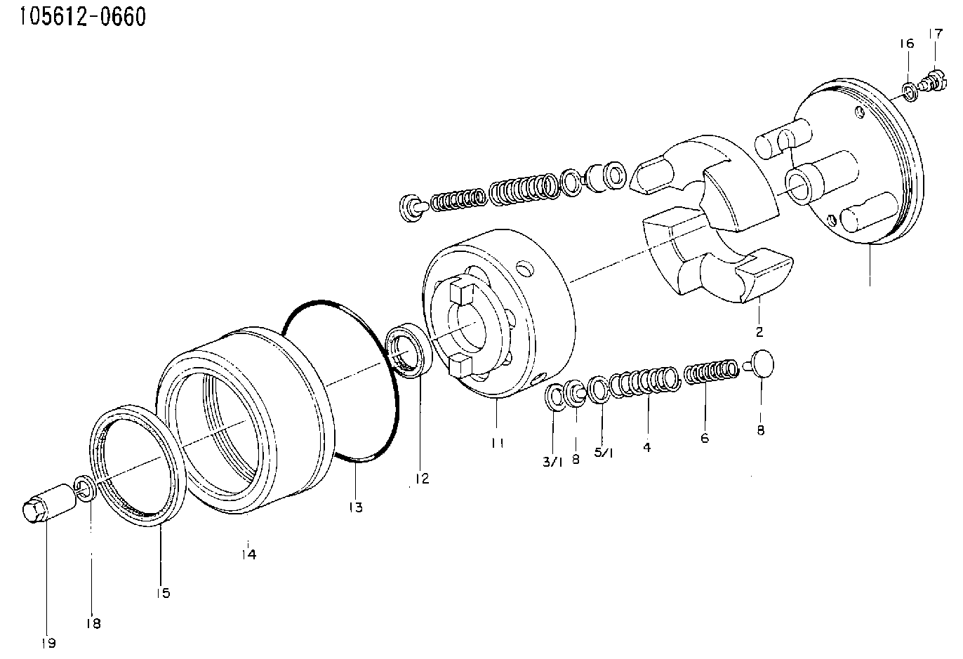
| 1. | [1] | 156132-6420 | FLYWEIGHT ASSEMBLY |
| 2. | [2] | 156108-3700 | FLYWEIGHT |
| 3/1. | [0] | 029310-9010 | SHIM D19.6&9T0.5 |
| 3/1. | [0] | 029310-9020 | SHIM D19.6&9T1 |
| 3/1. | [0] | 029310-9030 | SHIM D19.6&9T0.1 |
| 3/1. | [0] | 029310-9040 | SHIM D19.6&9T0.2 |
| 3/1. | [0] | 029310-9050 | PLAIN WASHER D19.6&9T1.5 |
| 3/1. | [0] | 139409-0000 | SHIM D19.6&9.0T0.15 |
| 4. | [2] | 156104-6100 | COMPRESSION SPRING |
| 5/1. | [0] | 029310-6010 | SHIM D12.6&6.6T0.30 |
| 5/1. | [0] | 029310-6020 | SHIM D12.6&6.6T0.50 |
| 5/1. | [0] | 029310-6340 | SHIM D12.6&6.6T1.0 |
| 5/1. | [0] | 029310-6350 | SHIM D12.6&6.6T1.5 |
| 6. | [2] | 156106-0910 | COMPRESSION SPRING |
| 8. | [2] | 156107-0800 | SLOTTED WASHER |
| 8. | [2] | 156107-0800 | SLOTTED WASHER |
| 11. | [1] | 156101-7920 | FLANGE BUSHING |
| 12. | [1] | 029622-8010 | PACKING RING |
| 13. | [1] | 156117-0100 | O-RING |
| 14. | [1] | 156114-0700 | CASE |
| 15. | [1] | 156116-0720 | PACKING RING |
| 16. | [2] | 026508-1240 | GASKET D11.9&8.2T1 |
| 17. | [2] | 156115-0100 | CAPSULE |
| 18. | [1] | 014111-2420 | LOCKING WASHER |
| 19. | [1] | 131325-0200 | UNION NUT |
Cross reference number
Zexel num
Bosch num
Firm num
Name
105612-0660
3116110302 MITSUBISHI
AUTOM. ADVANCE MECHANISM
K 14KC AUTOMATIC TIMER TIMER SA TIMER
K 14KC AUTOMATIC TIMER TIMER SA TIMER
Information:
2. Disconnect the fuel lines from fuel transfer pump (1).3. Remove two bolts (2) and fuel transfer pump (1). 4. Be sure O-ring seal (3) is in position on the fuel transfer pump and put clean oil on the O-ring seal.5. Put the fuel transfer pump in position on the fuel injection pump and install the two bolts that hold it in place.6. Connect the fuel lines to the fuel transfer pump.7. Open the fuel shutoff valve at the fuel tank.Disassemble Fuel Transfer Pump
start by:a) remove fuel transfer pump
Cover (2) is under spring tension.
1. Carefully remove bolts (1) and cover (2) from the fuel transfer pump. 2. Remove spring (3), valve (4) and O-ring seals (5) from the cover. 3. Remove springs (6) and (7) from the pump housing. 4. Remove sleeve (8) from the pump housing. 5. Remove sleeve (12), piston (16), O-ring seal (11) and piston (9) from sleeve (8). Remove plate (15), valve (10) and seal (14) from piston (9). Remove O-ring seal (13) from sleeve (8). 6. Remove O-ring seal (17) from the pump housing. 7. Push guide (18) through the pump housing and remove guides (23) and (18) together. Remove rod (20), guide (23), O-ring seal (19) and tappet (21) from guide (18). Remove ring (22) from tappet (21). 8. Remove connector (24), valve (26) and seal (25) from the pump housing. 9. Remove plug (30), spring (28), valve (29) and seal (27) from the pump housing.Assemble Fuel Transfer Pump
1. Clean all parts and be sure all passage are open. 2. Be sure the O-ring seal is in position on plug (4) and put 4L7464 Silicone Grease on the O-ring seal. Valves (2 and 6) must be installed as shown for the pump to work correctly.3. Install seal (1), valve (2), spring (3) and plug (4) in the pump housing as shown. Tighten plug (4) to a torque of 20 7 N m (15 5 lb.ft.). 4. Be sure the O-ring seal is in position on connector (7) and put 4L7464 Silicone Grease on the O-ring seal.5. Install seal (5), valve (6) and connector (7) in the pump housing as shown. Tighten connector (7) to a torque of 55 10 N m (40 7 lb.ft.). 6. Install the ring on tappet (8). Install tappet (8), O-ring seal (12), guide (9) and rod (10) in guide (11). Put 4L7464 Silicone Grease on O-ring seal (12). Install guides (11) and (9) as a unit in the pump housing as shown. 7. Install O-ring seal (13) in the pump housing and put 4L7464 Silicone Grease on the O-ring seal. 8. Install seal (15), valve (19) and plate (16) in piston (14) as shown. Install piston (14), O-ring seal (17), piston (20) and guide (21) in guide (18) as shown. Install the O-ring seal on guide (18) and put 4L7464 Silicone Grease on O-ring seal (17) and the O-ring seal on guide (18). 9. Install guide (18) in the pump housing as shown.