Information auto;timing device
BOSCH
9 420 616 336
9420616336
ZEXEL
105691-4131
1056914131
NISSAN-DIESEL
1685197664
1685197664
Rating:
Scheme ###:
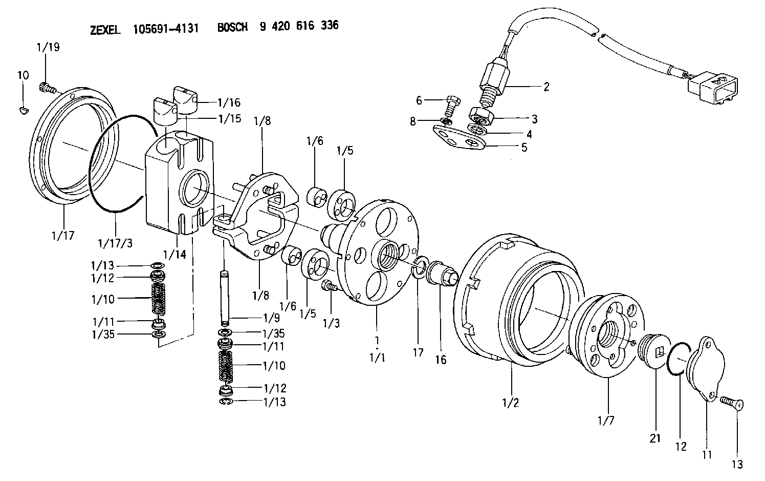
| 1. | [1] | 156995-5021 | AUTO;TIMING DEVICE |
| 1/1. | [1] | 156915-0100 | FLANGE BUSHING |
| 1/2. | [1] | 156901-8120 | TIMING-DEVICE HOUSING |
| 1/3. | [6] | 139006-2700 | BLEEDER SCREW |
| 1/5. | [2] | 156904-0700 | ECCENTRIC DISC |
| 1/5. | [2] | 156904-0700 | ECCENTRIC DISC |
| 1/6. | [2] | 156904-0100 | ECCENTRIC DISC |
| 1/6. | [2] | 156904-0100 | ECCENTRIC DISC |
| 1/7. | [1] | 156903-1120 | SLOTTED WASHER |
| 1/8. | [2] | 156907-3620 | PLATE |
| 1/8. | [2] | 156907-3620 | PLATE |
| 1/9. | [2] | 156910-2400 | PIN |
| 1/10. | [4] | 156908-6600 | COMPRESSION SPRING |
| 1/10. | [4] | 156908-6600 | COMPRESSION SPRING |
| 1/11. | [4] | 156909-0000 | SLOTTED WASHER |
| 1/11. | [4] | 156909-0000 | SLOTTED WASHER |
| 1/12. | [4] | 156707-0000 | SLOTTED WASHER |
| 1/12. | [4] | 156707-0000 | SLOTTED WASHER |
| 1/13. | [4] | 156913-7400 | LOCKING WASHER |
| 1/13. | [4] | 156913-7400 | LOCKING WASHER |
| 1/14. | [1] | 156905-1920 | CYLINDER |
| 1/15. | [2] | 156906-0300 | PUMP PLUNGER |
| 1/16. | [2] | 156906-0300 | PUMP PLUNGER |
| 1/17. | [1] | 156902-0820 | COVER |
| 1/17/3. | [1] | 139799-0100 | O-RING |
| 1/19. | [6] | 010235-0820 | HEX-SOCKET-HEAD CAP SCREW |
| 1/35. | [4] | 156913-7300 | SHIM |
| 1/35. | [4] | 156913-7300 | SHIM |
| 2. | [1] | 479771-2500 | PULSE GENERATOR |
| 3. | [1] | 029201-6150 | UNION NUT |
| 4. | [1] | 139316-0000 | PLAIN WASHER D25&16.5T5 |
| 5. | [1] | 156913-7100 | PLATE |
| 6. | [2] | 020018-2070 | BLEEDER SCREW M8P1.25L20 7T |
| 8. | [2] | 014020-8140 | PLAIN WASHER D16&8.5T1.2 |
| 10. | [1] | 134563-2300 | WOODRUFF KEY |
| 11. | [1] | 156913-3900 | CAP |
| 12. | [1] | 139756-0000 | O-RING |
| 13. | [2] | 012206-1220 | FLAT-HEAD SCREW |
| 16. | [1] | 156809-0100 | UNION NUT |
| 17. | [1] | 156809-0000 | LOCKING WASHER |
| 21. | [1] | 156914-7121 | CAPSULE |
Include in #1:
106871-5653
as AUTOM. ADVANCE MECHANIS
Cross reference number
Zexel num
Bosch num
Firm num
Name
105691-4131
9 420 616 336
1685197664 NISSAN-DIESEL
AUTO;TIMING DEVICE
K
K
Information:
1. Remove the bolt and lock that holds suction bell (1) to the oil pan plate. Remove two bolts (4) that hold the elbow to the oil pump.
Oil pump idler gear (2) can fall off the pump when the pump is removed. To prevent injury, always hold the gear on the pump when the pump is removed.
2. Remove the bolts and locks that hold the oil pump to the engine. Remove oil pump (3).3. Install idler gear (2) on oil pump (3). Put the oil pump in position on the engine as shown with idler gear (2) engaged with the crankshaft gear. Install the bolts and locks that hold the oil pump to the engine.4. Install bolts (4) that hold the elbow to the oil pump.5. Install the bolt and lock that hold suction bell (1) to the oil pan plate.End By:a. install oil panDisassemble Oil Pump
Start By:a. remove oil pump (3304) or remove oil pump (3306) 1. Remove idler gear (2). Remove the bearing from the idler gear with Tool (B).2. Remove suction bell (1).3. Remove the bolt and the washer from the oil pump drive gear. 4. Remove the drive gear from the shaft with Tool (A).5. Remove the key from the pump shaft.6. Remove bolts (3) from the pump body. 7. Remove body (8), two gears (7), the keys and spacer (4) from the pump.8. Remove two shafts (5) and the gears.9. Remove bolts (6), the cover and the pressure relief valve from the body. 10. Remove the bearings from the oil pump body assembly and the scavenge pump body assembly with Tool (B).Assemble Oil Pump
1. Install the bearings in the scavenge pump body assembly with Tool (A) and a press as follows:a. Put bearings (1) in position on the inside of the scavenge pump body assembly with the chamfer on the bearing toward the outside of the pump body. Install the bearing until it is 1.52 mm (.060 in) below the inside machined surface of the scavenge pump body assembly. Make sure the joints in the bearings are at an angle of 30° 15° from the center line through the bores in the scavenge pump body and toward the outlet passage of the pump. The outlet passage has a cavity between the bearing bores. 2. Install the bearings in oil pump body assembly with Tool (A) and a press as follows:a. Put bearings (2) in position on the inside of the oil pump body assembly with the chamfer on the bearings toward the outside of the pump body. Install the bearings until they are even with the outside of the pump body. Make sure the joints in the bearings are at an angle of 30° 15° from the centerline through the bearing bores and toward the outlet passage of the pump. The outlet passage has a cavity between the bearing bores.3. Check the condition of the relief valve. Check the condition and specifications for all the parts of the oil pump before
Have questions with 105691-4131?
Group cross 105691-4131 ZEXEL
Nissan-Diesel
Mitsubishi
Nissan-Diesel
105691-4131
9 420 616 336
1685197664
AUTO;TIMING DEVICE