Information auto;timing device
BOSCH
9 420 616 314
9420616314
ZEXEL
105691-4082
1056914082
NISSAN-DIESEL
1680197171
1680197171
Rating:
Scheme ###:
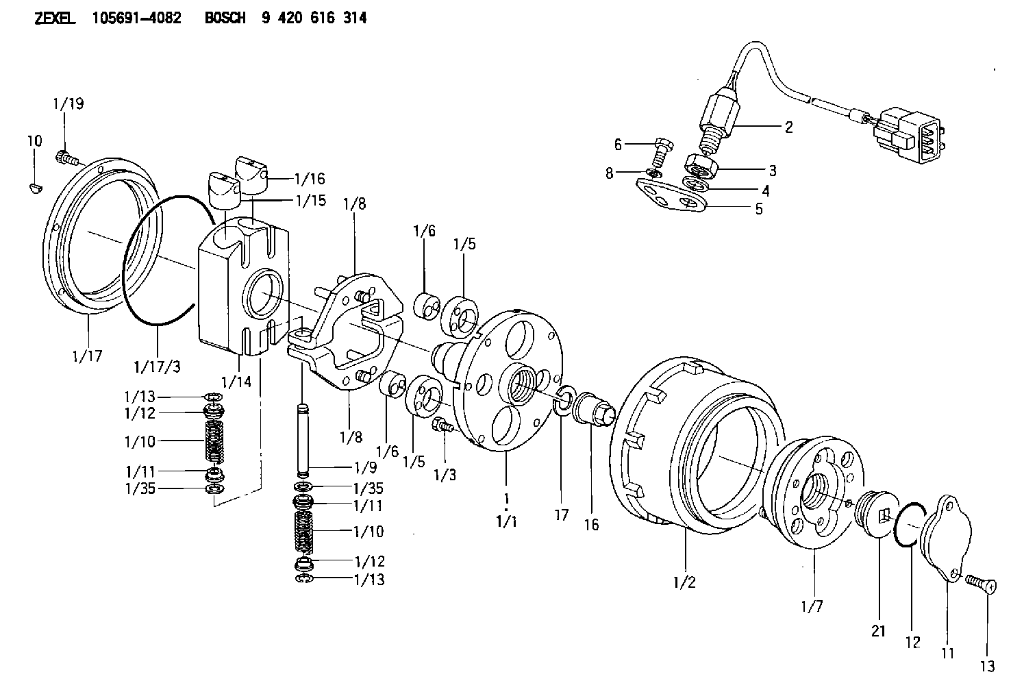
| 1. | [1] | 156995-4522 | AUTO;TIMING DEVICE |
| 1/1. | [1] | 156915-0000 | FLANGE BUSHING |
| 1/2. | [1] | 156901-8220 | TIMING-DEVICE HOUSING |
| 1/3. | [6] | 139006-2700 | BLEEDER SCREW |
| 1/5. | [2] | 156904-0700 | ECCENTRIC DISC |
| 1/5. | [2] | 156904-0700 | ECCENTRIC DISC |
| 1/6. | [2] | 156904-0100 | ECCENTRIC DISC |
| 1/6. | [2] | 156904-0100 | ECCENTRIC DISC |
| 1/7. | [1] | 156903-1120 | SLOTTED WASHER |
| 1/8. | [2] | 156907-3620 | PLATE |
| 1/8. | [2] | 156907-3620 | PLATE |
| 1/9. | [2] | 156910-2400 | PIN |
| 1/10. | [4] | 156908-6600 | COMPRESSION SPRING |
| 1/10. | [4] | 156908-6600 | COMPRESSION SPRING |
| 1/11. | [4] | 156909-0000 | SLOTTED WASHER |
| 1/11. | [4] | 156909-0000 | SLOTTED WASHER |
| 1/12. | [4] | 156707-0000 | SLOTTED WASHER |
| 1/12. | [4] | 156707-0000 | SLOTTED WASHER |
| 1/13. | [4] | 156913-7400 | LOCKING WASHER |
| 1/13. | [4] | 156913-7400 | LOCKING WASHER |
| 1/14. | [1] | 156905-1920 | CYLINDER |
| 1/15. | [2] | 156906-0300 | PUMP PLUNGER |
| 1/16. | [2] | 156906-0300 | PUMP PLUNGER |
| 1/17. | [1] | 156902-0820 | COVER |
| 1/17/3. | [1] | 139799-0100 | O-RING |
| 1/19. | [6] | 010235-0820 | HEX-SOCKET-HEAD CAP SCREW |
| 1/35. | [4] | 156913-7300 | SHIM |
| 1/35. | [4] | 156913-7300 | SHIM |
| 2. | [1] | 479771-0200 | PULSE GENERATOR |
| 3. | [1] | 029201-6150 | UNION NUT |
| 4. | [1] | 139316-0000 | PLAIN WASHER D25&16.5T5 |
| 5. | [1] | 156913-7100 | PLATE |
| 6. | [2] | 020018-2070 | BLEEDER SCREW M8P1.25L20 7T |
| 8. | [2] | 014020-8140 | PLAIN WASHER D16&8.5T1.2 |
| 10. | [1] | 134563-2300 | WOODRUFF KEY |
| 11. | [1] | 156913-3900 | CAP |
| 12. | [1] | 139756-0000 | O-RING |
| 13. | [2] | 012206-1220 | FLAT-HEAD SCREW |
| 16. | [1] | 156809-0100 | UNION NUT |
| 17. | [1] | 156809-0000 | LOCKING WASHER |
| 21. | [1] | 156914-7121 | CAPSULE |
Include in #1:
106971-5204
as AUTOM. ADVANCE MECHANIS
Cross reference number
Zexel num
Bosch num
Firm num
Name
105691-4082
9 420 616 314
1680197171 NISSAN-DIESEL
AUTO;TIMING DEVICE
K 14KN VARIABLE TIMER TIMER V/T TIMER
K 14KN VARIABLE TIMER TIMER V/T TIMER
105691-4082
9 420 616 314
1685197171 NISSAN-DIESEL
AUTO;TIMING DEVICE
A K 14KN VARIABLE TIMER TIMER V/T TIMER
A K 14KN VARIABLE TIMER TIMER V/T TIMER
Information:
Start By:a. remove timing gear cover1. Time the engine as follows:a. Install Tool (A) in the flywheel housing.b. Remove the cover from the side of the fuel injection pump housing so the timing pin can be installed. Remove the plug from the flywheel housing so the timing bolt can be installed.c. Turn the engine in the direction of engine rotation until Tool (B) can be installed in fuel injection pump housing and located in the groove in the fuel injection pump camshaft, a 3/8" - 16 NC bolt can be installed in the flywheel through the hole in the flywheel housing, and the "C" marks on the crankshaft gear and the camshaft gear are in alignment with each other. 2. Loosen bolt (1) until there is approximately 3.18 mm (.125 in) gap between washer (2) and fuel pump drive gear (3).3. Install Tool (C) as shown, and loosen the fuel pump drive gear from the taper on the fuel injection pump camshaft. Remove Tool (C), the bolt, washer and fuel pump drive gear.4. Remove the bolts and plate (4) that hold idler gear (5) in position. Remove the idler gear. If necessary, remove the bearing from the idler gear with Tool (D) and a press.
Do not turn the crankshaft after camshaft gear (6) has been removed. Turning the crankshaft will cause damage to the valves.
5. Remove the four bolts that hold camshaft gear (6) to the camshaft. Remove the camshaft gear.Install Timing Gears
1. Make an alignment of the "C" marks on crankshaft gear (3) and camshaft gear (4). Install the camshaft gear and the bolts that hold it. Tighten the bolts to a torque of 55 7 N m (41 5 lb ft).2. Install the bearing in idler gear (1) with Tool (A). The end of the bearing must be 1.52 mm (.060 in) below the face of the gear hub after installation.3. Be sure the oil hole in the shaft for idler gear (1) is open. Put idler gear (1) and plate (2) in position on the shaft. Install the bolts that hold them. 4. Make sure Tool (C) is in position in the groove of the fuel injection pump camshaft.5. Put fuel injection pump drive gear (5) in position on the fuel injection pump camshaft. Put washer (6) in position on the gear with the largest diameter toward the front of the engine. Install bolt (7), and tighten it to a torque of 7 N m (5 lb ft). Make sure bolt (7) does not turn while the flywheel is being turned.6. Remove the timing bolt from the flywheel, and use Tool (B) to turn the flywheel in the opposite direction of engine rotation. Turn the flywheel until the "C" mark on the crankshaft gear moves 30°.7. Turn the flywheel in the direction of engine rotation until the timing bolt can be installed in the flywheel and the "C" marks are in alignment. This will remove all of the backlash from the timing gears.8.
Have questions with 105691-4082?
Group cross 105691-4082 ZEXEL
Mitsubishi
Nissan-Diesel
Nissan-Diesel
Nissan-Diesel
Mitsubishi
Nissan-Diesel
Nissan-Diesel
Nissan-Diesel
105691-4082
9 420 616 314
1680197171
AUTO;TIMING DEVICE
105691-4082
9 420 616 314
1685197171
AUTO;TIMING DEVICE