Information auto;timing device
BOSCH
9 420 617 018
9420617018
ZEXEL
105691-4072
1056914072
NISSAN-DIESEL
1685197609
1685197609
Rating:
Scheme ###:
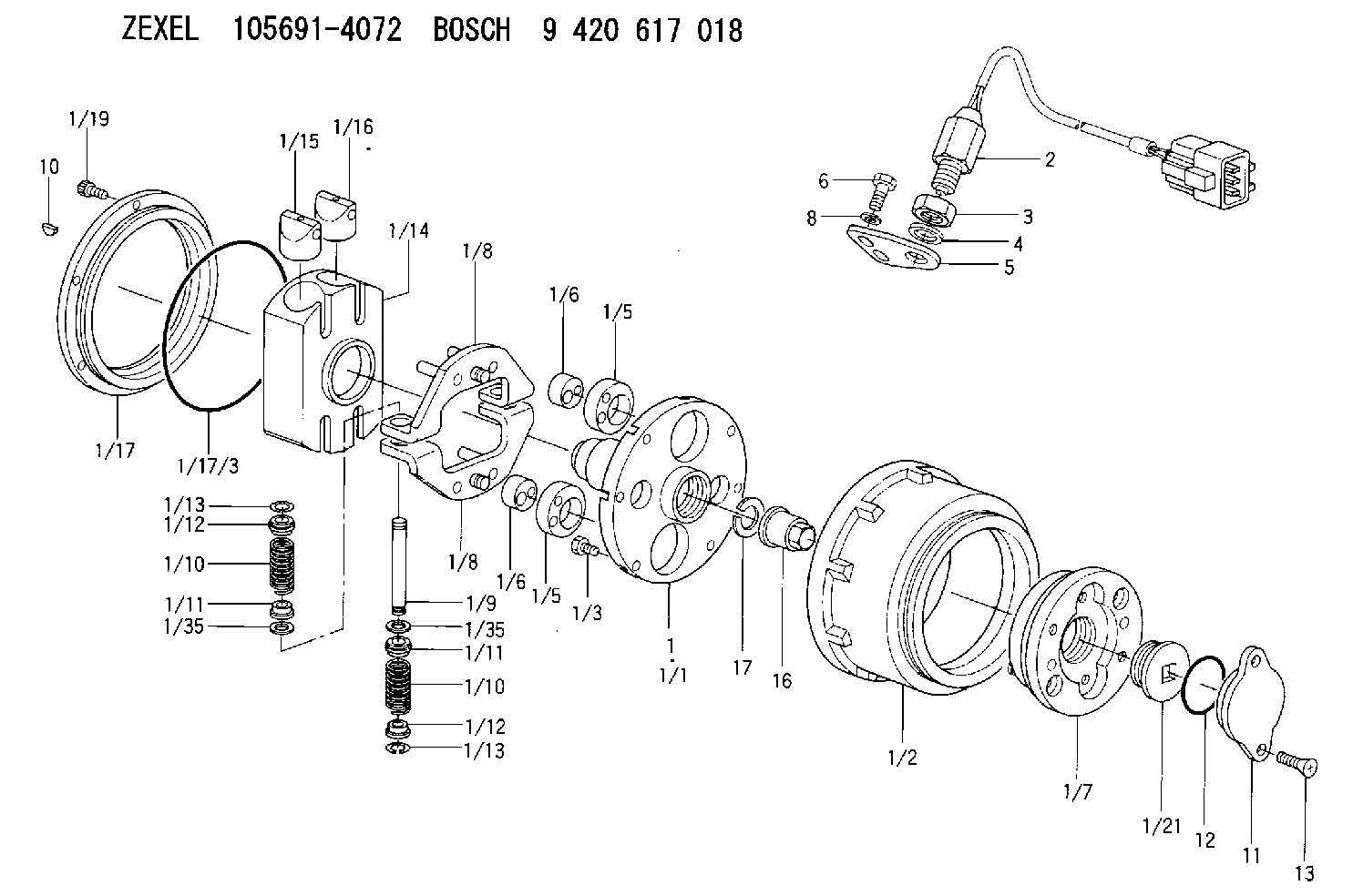
| 1. | [1] | 156995-4422 | AUTO;TIMING DEVICE |
| 1/1. | [1] | 156900-9700 | FLANGE BUSHING |
| 1/2. | [1] | 156901-8120 | TIMING-DEVICE HOUSING |
| 1/3. | [6] | 139006-2700 | BLEEDER SCREW |
| 1/5. | [2] | 156904-0700 | ECCENTRIC DISC |
| 1/5. | [2] | 156904-0700 | ECCENTRIC DISC |
| 1/6. | [2] | 156904-0100 | ECCENTRIC DISC |
| 1/6. | [2] | 156904-0100 | ECCENTRIC DISC |
| 1/7. | [1] | 156903-1120 | SLOTTED WASHER |
| 1/8. | [2] | 156907-3620 | PLATE |
| 1/8. | [2] | 156907-3620 | PLATE |
| 1/9. | [2] | 156910-2400 | PIN |
| 1/10. | [4] | 156908-6600 | COMPRESSION SPRING |
| 1/10. | [4] | 156908-6600 | COMPRESSION SPRING |
| 1/11. | [4] | 156909-0000 | SLOTTED WASHER |
| 1/11. | [4] | 156909-0000 | SLOTTED WASHER |
| 1/12. | [4] | 156707-0000 | SLOTTED WASHER |
| 1/12. | [4] | 156707-0000 | SLOTTED WASHER |
| 1/13. | [4] | 156913-7400 | LOCKING WASHER |
| 1/13. | [4] | 156913-7400 | LOCKING WASHER |
| 1/14. | [1] | 156905-1920 | CYLINDER |
| 1/15. | [2] | 156906-0300 | PUMP PLUNGER |
| 1/16. | [2] | 156906-0300 | PUMP PLUNGER |
| 1/17. | [1] | 156902-0820 | COVER |
| 1/17/3. | [1] | 139799-0100 | O-RING |
| 1/19. | [6] | 010235-0820 | HEX-SOCKET-HEAD CAP SCREW |
| 1/21. | [1] | 156914-6500 | CAPSULE |
| 1/35. | [4] | 156913-7300 | SHIM |
| 1/35. | [4] | 156913-7300 | SHIM |
| 2. | [1] | 479771-2500 | PULSE GENERATOR |
| 3. | [1] | 029201-6150 | UNION NUT |
| 4. | [1] | 139316-0000 | PLAIN WASHER D25&16.5T5 |
| 5. | [1] | 156913-7100 | PLATE |
| 6. | [2] | 020018-2070 | BLEEDER SCREW M8P1.25L20 7T |
| 8. | [2] | 014020-8140 | PLAIN WASHER D16&8.5T1.2 |
| 10. | [1] | 134563-2300 | WOODRUFF KEY |
| 11. | [1] | 156913-3900 | CAP |
| 12. | [1] | 139756-0000 | O-RING |
| 13. | [2] | 012206-1220 | FLAT-HEAD SCREW |
| 16. | [1] | 156809-0100 | UNION NUT |
| 17. | [1] | 156809-0000 | LOCKING WASHER |
Include in #1:
106871-5543
as AUTOM. ADVANCE MECHANIS
Cross reference number
Zexel num
Bosch num
Firm num
Name
105691-4072
9 420 617 018
1685197609 NISSAN-DIESEL
AUTO;TIMING DEVICE
K
K
Information:
Start By:a. remove oil pumpb. remove oil pan plate 1. Remove No. 1, 3, 5 and 7 main bearing caps (1). Remove the lower halves of the main bearings from the main bearing caps.
If the crankshaft is turned in the wrong direction, the tab on the bearing will be pushed between the crankshaft and the bearing area in the cylinder block. This can result in damage to the cylinder block and/or the crankshaft.
2. Install Tool (A) in the hole in the crankshaft journal, and turn the crankshaft to remove the upper halves of main bearings (2).3. Remove crankshaft thrust bearings (3) from the rear main bearing. Install the main bearings dry when the clearance checks are made. Put clean engine oil on the main bearings for final assembly.
Make sure the upper and lower halves of the main bearings are installed so the bearing tabs fit into the notch in the cylinder block and the main bearing caps.
4. Use Tool (A), and install new upper halves of main bearings (2) in the cylinder block. Install new lower halves of main bearings (2) in main bearing caps (1).
When the bearing clearance is checked and the engine is in an upright position (vertical position with cylinder head on top), the crankshaft will have to be lifted up and held against the upper halves of the main bearings to get a correct measurement with the Plastigage. The Plastigage will not hold the weight of the crankshaft and give a correct indication. If the engine is in a horizontal position, it is not necessary to hold the crankshaft up. Do not turn the crankshaft when the Plastigage is in position to check clearances.
For complete details concerning measuring bearing clearances, see Engine Bearings And Crankshafts, Form No. SEBD0531.5. Check the main bearing clearance with Plastigage (B) as follows:a. Put a piece of Plastigage (B) on the crankshaft journals as shown.
Make sure the part number on the main bearing cap is toward the front of the engine and the number on the main bearing cap is the same as the number on the cylinder block on the left side of each main bearing cap.
b. Put main bearing caps (1) in position in the engine. Put 2P2506 Thread Lubricant on the bolt threads and the face of the washers. Install the bolts. Tighten the bolts to a torque of 40 4 N m (30 3 lb ft).c. Put a mark on each bolt and main bearing cap; then tighten the bolts 90° more.d. Remove the main bearing caps, and measure the Plastigage to find the bearing clearance. The main bearing clearance for new bearings must be 0.076 to 0.165 mm (.0030 to .0065 in.). Maximum permissible clearance with used bearings is 0.25 mm (.010 in.). 6. Put clean oil on the thrust bearing, and install a new thrust bearing for the rear main bearing. Install the thrust bearing with the identification "BLOCK SIDE" toward the cylinder block and the tabs on the thrust bearings
Have questions with 105691-4072?
Group cross 105691-4072 ZEXEL
Mitsubishi
Nissan-Diesel
Nissan-Diesel
Nissan-Diesel
Mitsubishi
Nissan-Diesel
Nissan-Diesel
105691-4072
9 420 617 018
1685197609
AUTO;TIMING DEVICE