Information auto;timing device
BOSCH
9 420 615 928
9420615928
ZEXEL
105691-4071
1056914071

Rating:
Scheme ###:
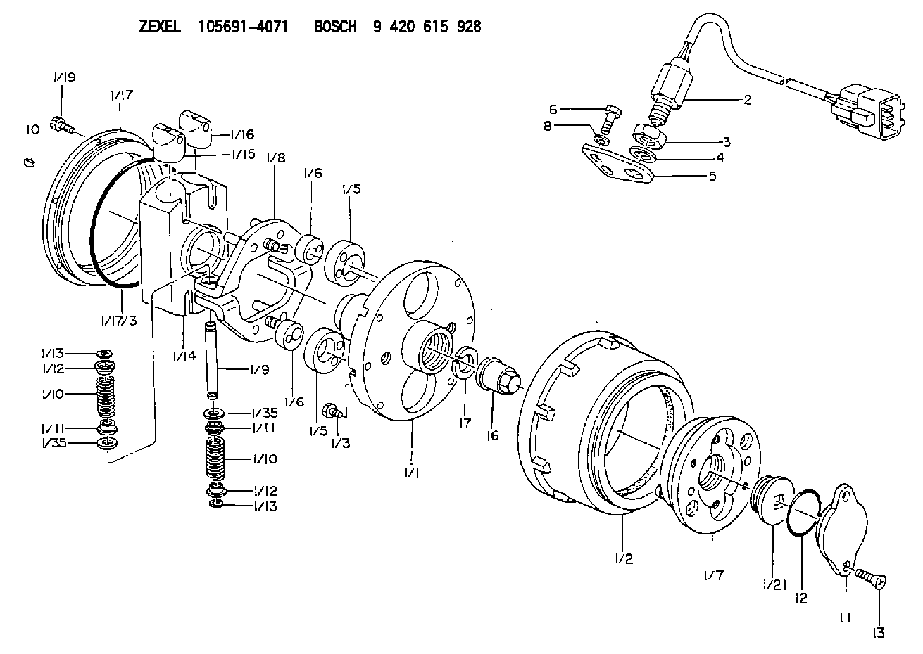
| 1. | [1] | 156995-4421 | AUTO;TIMING DEVICE |
| 1/1. | [1] | 156900-9000 | FLANGE BUSHING |
| 1/2. | [1] | 156901-8120 | TIMING-DEVICE HOUSING |
| 1/3. | [6] | 139006-2700 | BLEEDER SCREW |
| 1/5. | [2] | 156904-0700 | ECCENTRIC DISC |
| 1/5. | [2] | 156904-0700 | ECCENTRIC DISC |
| 1/6. | [2] | 156904-0100 | ECCENTRIC DISC |
| 1/6. | [2] | 156904-0100 | ECCENTRIC DISC |
| 1/7. | [1] | 156903-1120 | SLOTTED WASHER |
| 1/8. | [2] | 156907-3620 | PLATE |
| 1/9. | [2] | 156910-2400 | PIN |
| 1/10. | [4] | 156908-6600 | COMPRESSION SPRING |
| 1/10. | [4] | 156908-6600 | COMPRESSION SPRING |
| 1/11. | [4] | 156909-0000 | SLOTTED WASHER |
| 1/11. | [4] | 156909-0000 | SLOTTED WASHER |
| 1/12. | [4] | 156707-0000 | SLOTTED WASHER |
| 1/12. | [4] | 156707-0000 | SLOTTED WASHER |
| 1/13. | [4] | 156913-7400 | LOCKING WASHER |
| 1/13. | [4] | 156913-7400 | LOCKING WASHER |
| 1/14. | [1] | 156905-1720 | CYLINDER |
| 1/15. | [2] | 156906-0300 | PUMP PLUNGER |
| 1/16. | [2] | 156906-0300 | PUMP PLUNGER |
| 1/17. | [1] | 156902-0820 | COVER |
| 1/17/3. | [1] | 139799-0100 | O-RING |
| 1/19. | [6] | 010235-0820 | HEX-SOCKET-HEAD CAP SCREW |
| 1/21. | [1] | 156913-0900 | CAPSULE |
| 1/35. | [4] | 156913-7300 | SHIM |
| 1/35. | [4] | 156913-7300 | SHIM |
| 2. | [1] | 479771-2500 | PULSE GENERATOR |
| 3. | [1] | 029201-6150 | UNION NUT |
| 4. | [1] | 139316-0000 | PLAIN WASHER D25&16.5T5 |
| 5. | [1] | 156913-7100 | PLATE |
| 6. | [2] | 020018-2070 | BLEEDER SCREW M8P1.25L20 7T |
| 8. | [2] | 014020-8140 | PLAIN WASHER D16&8.5T1.2 |
| 10. | [1] | 134563-2300 | WOODRUFF KEY |
| 11. | [1] | 156913-3900 | CAP |
| 12. | [1] | 139756-0000 | O-RING |
| 13. | [2] | 012206-1220 | FLAT-HEAD SCREW |
| 16. | [1] | 156809-0100 | UNION NUT |
| 17. | [1] | 156809-0000 | LOCKING WASHER |
Cross reference number
Zexel num
Bosch num
Firm num
Name
Information:
Start By:a. remove pistons1. Drain the coolant from the cylinder block.2. Put covers on the journals of the crankshaft for protection from dirt or water. 3. Remove cylinder liners (1) with Tool (A).4. Remove the O-ring seals and filler band from each of the cylinder liners.Install Cylinder Liners
1. Clean cylinder liners (3) and the liner bores in the cylinder block.2. Install the cylinder liners in the block without the O-ring seals or filler bands.3. Check the cylinder liner projection as follows:a. Install the S1589 Bolts (2) and 1S379 Washers of Tool (B) on the cylinder block next to each liner. Tighten the bolts evenly, in four steps: 14 N m (10 lb ft), 35 N m (25 lb ft), 70 N m (52 lb ft) and 95 N m (70 lb ft).b. Put the adapter plate on top of the liner, and install the remainder of Tool (B). Tighten the 1D4595 Bolts (1) evenly in four steps: 7 N m (5 lb ft), 20 N m (15 lb ft), 35 N m (25 lb ft) and 70 N m (52 lb ft).c. Check to be sure the distance from the bottom edge of the crossbar to the top of the cylinder block is the same on both sides of the liner.d. Check the cylinder liner projection with Tool (C) at four locations around the liner.e. Liner projection must be 0.033 to 0.175 mm (.0013 to .0069 in). Measurements on the same liner must not be different by more than 0.05 mm (.002 in). Average measurements between liners next to each other must not be different by more than 0.05 mm (.002 in). The maximum permissible difference between average projection of all cylinder liners is 0.10 mm (.004 in). If the liner is turned in the bore, it can make a difference in the liner projection.4. If the projection is not 0.033 to 0.175 mm (.0013 to .0069 in), check the thickness of the following parts: spacer plate, spacer plate gasket and cylinder liner flange. The thickness of the spacer plate must be 9.970 0.025 mm (.3925 .0010 in). The thickness of the spacer plate gasket must be 0.208 0.025 mm (.0082 .0010 in). The thickness of the cylinder liner flange must be 10.282 0.020 mm (.4048 .0008 in). If the liner projection changes from point to point around the liner, turn the liner to a new position in the bore. If the liner projection is still not to specifications, move the liner to a different bore.5. When the cylinder projection is correct, put an alignment mark on the liner and block so the liner can be installed in the same position from which it was removed. Cylinder liner projection can be adjusted by the removal of material from (machining) the contact face of the cylinder block with the use of the 8S3140 Cylinder Block Counterboring Tool Arrangement. Machine to a minimum depth of 0.76 mm (.030 in) and to a maximum
1. Clean cylinder liners (3) and the liner bores in the cylinder block.2. Install the cylinder liners in the block without the O-ring seals or filler bands.3. Check the cylinder liner projection as follows:a. Install the S1589 Bolts (2) and 1S379 Washers of Tool (B) on the cylinder block next to each liner. Tighten the bolts evenly, in four steps: 14 N m (10 lb ft), 35 N m (25 lb ft), 70 N m (52 lb ft) and 95 N m (70 lb ft).b. Put the adapter plate on top of the liner, and install the remainder of Tool (B). Tighten the 1D4595 Bolts (1) evenly in four steps: 7 N m (5 lb ft), 20 N m (15 lb ft), 35 N m (25 lb ft) and 70 N m (52 lb ft).c. Check to be sure the distance from the bottom edge of the crossbar to the top of the cylinder block is the same on both sides of the liner.d. Check the cylinder liner projection with Tool (C) at four locations around the liner.e. Liner projection must be 0.033 to 0.175 mm (.0013 to .0069 in). Measurements on the same liner must not be different by more than 0.05 mm (.002 in). Average measurements between liners next to each other must not be different by more than 0.05 mm (.002 in). The maximum permissible difference between average projection of all cylinder liners is 0.10 mm (.004 in). If the liner is turned in the bore, it can make a difference in the liner projection.4. If the projection is not 0.033 to 0.175 mm (.0013 to .0069 in), check the thickness of the following parts: spacer plate, spacer plate gasket and cylinder liner flange. The thickness of the spacer plate must be 9.970 0.025 mm (.3925 .0010 in). The thickness of the spacer plate gasket must be 0.208 0.025 mm (.0082 .0010 in). The thickness of the cylinder liner flange must be 10.282 0.020 mm (.4048 .0008 in). If the liner projection changes from point to point around the liner, turn the liner to a new position in the bore. If the liner projection is still not to specifications, move the liner to a different bore.5. When the cylinder projection is correct, put an alignment mark on the liner and block so the liner can be installed in the same position from which it was removed. Cylinder liner projection can be adjusted by the removal of material from (machining) the contact face of the cylinder block with the use of the 8S3140 Cylinder Block Counterboring Tool Arrangement. Machine to a minimum depth of 0.76 mm (.030 in) and to a maximum