Information auto;timing device
BOSCH
9 420 616 269
9420616269
ZEXEL
105691-4011
1056914011
NISSAN-DIESEL
1685196868
1685196868
Rating:
Scheme ###:
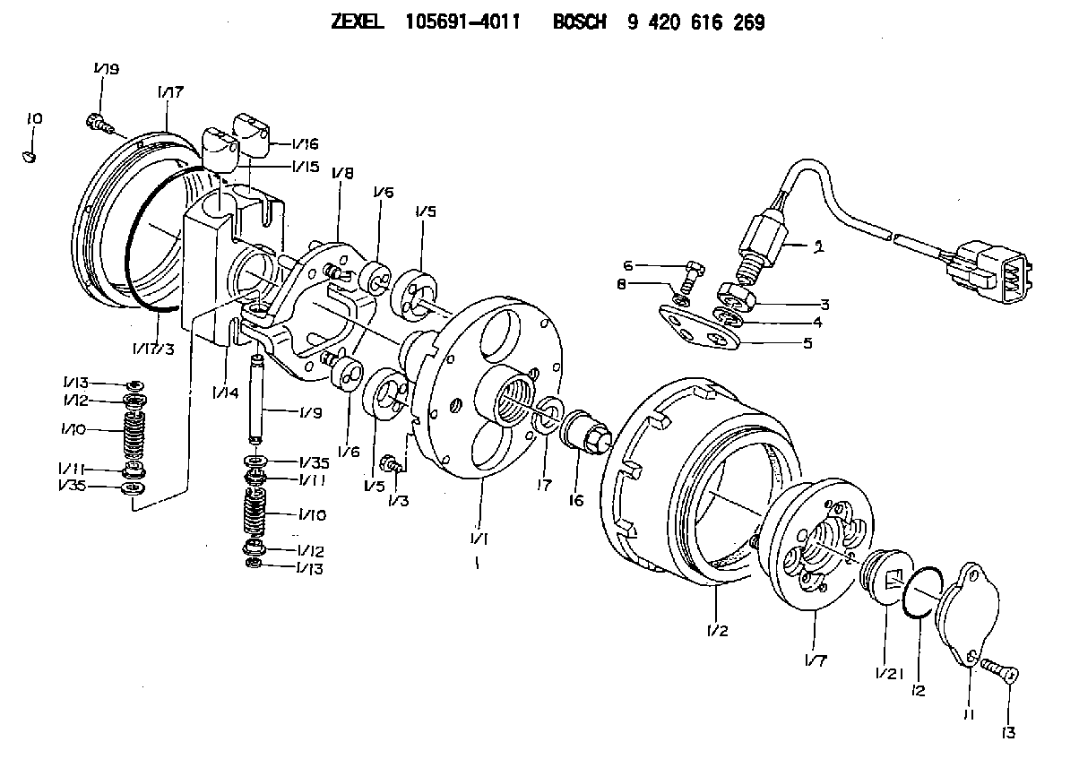
| 1. | [1] | 156995-3821 | AUTO;TIMING DEVICE |
| 1/1. | [1] | 156900-9200 | FLANGE BUSHING |
| 1/2. | [1] | 156901-8420 | TIMING-DEVICE HOUSING |
| 1/3. | [6] | 139006-2700 | BLEEDER SCREW |
| 1/5. | [2] | 156904-0700 | ECCENTRIC DISC |
| 1/5. | [2] | 156904-0700 | ECCENTRIC DISC |
| 1/6. | [2] | 156904-0100 | ECCENTRIC DISC |
| 1/6. | [2] | 156904-0100 | ECCENTRIC DISC |
| 1/7. | [1] | 156903-2620 | SLOTTED WASHER |
| 1/8. | [2] | 156907-3220 | PLATE |
| 1/9. | [2] | 156910-2400 | PIN |
| 1/10. | [4] | 156908-6600 | COMPRESSION SPRING |
| 1/10. | [4] | 156908-6600 | COMPRESSION SPRING |
| 1/11. | [4] | 156909-0000 | SLOTTED WASHER |
| 1/11. | [4] | 156909-0000 | SLOTTED WASHER |
| 1/12. | [4] | 156707-0000 | SLOTTED WASHER |
| 1/12. | [4] | 156707-0000 | SLOTTED WASHER |
| 1/13. | [4] | 156913-7400 | LOCKING WASHER |
| 1/13. | [4] | 156913-7400 | LOCKING WASHER |
| 1/14. | [1] | 156905-1920 | CYLINDER |
| 1/15. | [2] | 156906-0300 | PUMP PLUNGER |
| 1/16. | [2] | 156906-0300 | PUMP PLUNGER |
| 1/17. | [1] | 156902-0820 | COVER |
| 1/17/3. | [1] | 139799-0100 | O-RING |
| 1/19. | [6] | 010235-0820 | HEX-SOCKET-HEAD CAP SCREW |
| 1/21. | [1] | 156913-0900 | CAPSULE |
| 1/35. | [4] | 156913-7300 | SHIM |
| 1/35. | [4] | 156913-7300 | SHIM |
| 2. | [1] | 479771-0000 | PULSE GENERATOR |
| 3. | [1] | 029201-6150 | UNION NUT |
| 4. | [1] | 139316-0000 | PLAIN WASHER D25&16.5T5 |
| 5. | [1] | 156913-7100 | PLATE |
| 6. | [2] | 020018-2070 | BLEEDER SCREW M8P1.25L20 7T |
| 8. | [2] | 014020-8140 | PLAIN WASHER D16&8.5T1.2 |
| 10. | [1] | 134563-2300 | WOODRUFF KEY |
| 11. | [1] | 156913-9600 | CAP |
| 12. | [1] | 139756-0000 | O-RING |
| 13. | [2] | 012206-1220 | FLAT-HEAD SCREW |
| 16. | [1] | 156809-0100 | UNION NUT |
| 17. | [1] | 156809-0000 | LOCKING WASHER |
Include in #1:
106671-5753
as AUTOM. ADVANCE MECHANIS
Cross reference number
Zexel num
Bosch num
Firm num
Name
105691-4011
9 420 616 269
1685196868 NISSAN-DIESEL
AUTO;TIMING DEVICE
K 14KN VARIABLE TIMER TIMER V/T TIMER
K 14KN VARIABLE TIMER TIMER V/T TIMER
Information:
Start By:a. remove fuel injection linesb. remove fuel filter and basec. remove fuel transfer pump The following illustrations are of a 3304 Engine. 1. Disconnect the governor control linkage from the governor.2. On 3304 Engines only: remove oil supply line (1), oil drain line (2) and heat shield (3). Remove the O-ring seal from oil drain line (2) if it is damaged. Remove the gaskets and screen from the top of the turbocharger.3. Disconnect fuel drain lines (4) and (5) from the fuel injection pump housing and governor. 4. Remove the nuts, washers and cover from the timing gear housing. Remove studs (6) if they are damaged or loose.5. Loosen bolt (7) enough to leave a gap of 3.18 mm (.125 in) between washer (8) and the fuel pump drive gear.6. Install Tool (A) as shown. Tighten the stud to pull the fuel pump drive gear loose from the taper on the fuel injection pump camshaft.7. Remove Tool (A), bolt (7) and washer (8) from the engine. 8. Fasten a nylon strap and hoist to the fuel injection pump housing and governor. The 3304 fuel injection pump housing and governor weighs 24 kg (53 lb). The 3306 fuel injection pump housing and governor weighs 29 kg (64 lb).9. Remove bolt (9), bolt (10), three nuts (11) and the fuel injection pump housing and governor. Remove the two O-ring seals from the bottom and the two O-ring seals from the front of the fuel injection pump housing and governor.Install Fuel Injection Pump Housing & Governor
The following illustrations are of a 3304 Engine. 1. Put clean engine oil on the O-ring seals. Install O-ring seals (1) in the bottom and O-ring seals (2) in the front of the fuel injection pump housing and governor. 2. Make sure O-ring seals (1) and (2) stay in position in the fuel injection pump housing and governor. Fasten a hoist to the fuel injection pump housing and governor, and put it in position on the engine. Install the two bolts at location (5) and the three nuts on studs (3) to hold the fuel injection pump housing and governor in position.3. Remove the bolts that hold cover (4) in position. Remove cover (4) and the gasket. 4. Put Tool (A) in position as shown. Install the bolt that holds the fuel pump drive gear to the fuel injection pump camshaft without the washer. This will allow the camshaft in the fuel system to be turned.5. Put pressure on the end of Tool (A) and turn the camshaft slowly until the Tool drops into the groove (slot) in the camshaft. Leave Tool (A) in position in the groove (slot). Remove the bolt from the end of the camshaft. 6. Install washer (6) with the large diameter toward the front of the engine. Install bolt (7) and tighten it to a torque of 6.8 N m (60 lb in).7. Install Tool (B) as shown in the flywheel housing. Make sure bolt (7) does not loosen as
The following illustrations are of a 3304 Engine. 1. Put clean engine oil on the O-ring seals. Install O-ring seals (1) in the bottom and O-ring seals (2) in the front of the fuel injection pump housing and governor. 2. Make sure O-ring seals (1) and (2) stay in position in the fuel injection pump housing and governor. Fasten a hoist to the fuel injection pump housing and governor, and put it in position on the engine. Install the two bolts at location (5) and the three nuts on studs (3) to hold the fuel injection pump housing and governor in position.3. Remove the bolts that hold cover (4) in position. Remove cover (4) and the gasket. 4. Put Tool (A) in position as shown. Install the bolt that holds the fuel pump drive gear to the fuel injection pump camshaft without the washer. This will allow the camshaft in the fuel system to be turned.5. Put pressure on the end of Tool (A) and turn the camshaft slowly until the Tool drops into the groove (slot) in the camshaft. Leave Tool (A) in position in the groove (slot). Remove the bolt from the end of the camshaft. 6. Install washer (6) with the large diameter toward the front of the engine. Install bolt (7) and tighten it to a torque of 6.8 N m (60 lb in).7. Install Tool (B) as shown in the flywheel housing. Make sure bolt (7) does not loosen as
Have questions with 105691-4011?
Group cross 105691-4011 ZEXEL
Mitsubishi
Nissan-Diesel
105691-4011
9 420 616 269
1685196868
AUTO;TIMING DEVICE