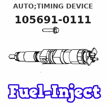
Information auto;timing device
BOSCH
9 420 616 472
9420616472
ZEXEL
105691-0111
1056910111
ISUZU
1157401470
1157401470

Rating:
Scheme ###:
| 1. | [1] | 156991-0220 | AUTO;TIMING DEVICE |
| 1/1. | [1] | 156900-2400 | FLANGE BUSHING |
| 1/2. | [1] | 156901-0020 | TIMING-DEVICE HOUSING |
| 1/3. | [6] | 139006-2700 | BLEEDER SCREW |
| 1/5. | [2] | 156904-0000 | ECCENTRIC DISC |
| 1/5. | [2] | 156904-0000 | ECCENTRIC DISC |
| 1/6. | [2] | 156904-0100 | ECCENTRIC DISC |
| 1/6. | [2] | 156904-0100 | ECCENTRIC DISC |
| 1/7. | [1] | 156903-1020 | SLOTTED WASHER |
| 1/8. | [2] | 156907-1120 | PLATE |
| 1/9. | [2] | 156910-2000 | PIN |
| 1/10. | [4] | 156908-3100 | COMPRESSION SPRING |
| 1/10. | [4] | 156908-3100 | COMPRESSION SPRING |
| 1/11. | [4] | 156909-0000 | SLOTTED WASHER |
| 1/11. | [4] | 156909-0000 | SLOTTED WASHER |
| 1/12. | [4] | 156707-0000 | SLOTTED WASHER |
| 1/12. | [4] | 156707-0000 | SLOTTED WASHER |
| 1/13. | [4] | 156913-7400 | LOCKING WASHER |
| 1/13. | [4] | 156913-7400 | LOCKING WASHER |
| 1/14. | [1] | 156905-0300 | CYLINDER |
| 1/15. | [2] | 156906-0300 | PUMP PLUNGER |
| 1/16. | [2] | 156906-0300 | PUMP PLUNGER |
| 1/17. | [1] | 156902-0820 | COVER |
| 1/17/3. | [1] | 139799-0100 | O-RING |
| 1/19. | [6] | 010235-0820 | HEX-SOCKET-HEAD CAP SCREW |
| 1/21. | [1] | 156913-0900 | CAPSULE |
| 1/24. | [1] | 156912-0800 | TIMING PLATE |
| 1/25. | [4] | 010006-0800 | BLEEDER SCREW |
| 1/26. | [4] | 139306-0300 | PLAIN WASHER |
| 1/35. | [4] | 156913-7300 | SHIM |
| 2. | [1] | 479729-3200 | PULSE GENERATOR |
| 3. | [1] | 029201-6150 | UNION NUT |
| 4. | [1] | 139316-0000 | PLAIN WASHER D25&16.5T5 |
| 5. | [1] | 156913-4300 | PLATE |
| 6. | [2] | 020018-2070 | BLEEDER SCREW M8P1.25L20 7T |
| 7. | [2] | 156913-4200 | BUSHING |
| 10. | [1] | 134563-2300 | WOODRUFF KEY |
| 11. | [1] | 156913-3900 | CAP |
| 12. | [1] | 139756-0000 | O-RING |
| 13. | [2] | 012206-1220 | FLAT-HEAD SCREW |
| 16. | [1] | 156809-0100 | UNION NUT |
| 17. | [1] | 156809-0000 | LOCKING WASHER |
Include in #1:
106671-1312
as AUTOM. ADVANCE MECHANIS
Cross reference number
Zexel num
Bosch num
Firm num
Name
105691-0111
9 420 616 472
1157401470 ISUZU
AUTO;TIMING DEVICE
* K 14KN TIMER V/T TIMER
* K 14KN TIMER V/T TIMER
105691-0111
9 420 616 472
1157401780 ISUZU
AUTO;TIMING DEVICE
A * K 14KN TIMER V/T TIMER
A * K 14KN TIMER V/T TIMER
Information:
Inspection of adjustment voltage (a) Disconnect the cable from the positive (+) terminal of the battery, and connect an ammeter between the terminal and cable.(b) Connect a voltmeter between terminal L and ground.(c) Make sure that the voltmeter indicates "0" when the starter switch is turned off. Make sure that the voltmeter indicates a voltage level significantly lower than the battery voltage when the starter switch is turned on (without starting the engine).(d) Short-circuit the terminal of the ammeter, and start the engine.(e) Read the indication (adjustment voltage) on the voltmeter with the ammeter indicating 5A or lower, the engine operating at 1500 to 2500 min-1, and the lamp switches turned off.(3) Inspection of output (unit with integrated IC regulator)
Wiring for output test (a) Disconnect the grounding cable from the battery.(b) Disconnect the wire from terminal B of the alternator, and connect an ammeter, then connect a voltmeter between B and ground.(c) Reconnect the grounding cable to the battery.(d) Start the engine.(e) Immediately after the engine starts, turn on all load devices such as lamps.(f) Increase the engine speed, and read the maximum current at the specified alternator rotation speed when the voltmeter indicates 27.0 V. If the measured value conforms to the standard value, the alternator is normal.Disassembly of Alternator
(1) Separation of front bracket from stator coreInsert the tip of a slotted screwdriver into the gap between the stator core and front bracket, and pry open.
Separation of front bracket from stator core
Do not insert the screwdriver too far into the assembly to prevent damaging the stator core.
(2) Removal of the pulley
Removal of pulley(a) After wrapping the rotor with a cloth for protection and holding it with a vice, unscrew the pulley nut, then remove the pulley and spacer.(b) Remove the rotor from the front bracket.(3) Removal of stator core and rectifier
Removal of stator core(a) Disconnect the lead wires between the stator core and the rectifier at the soldered sections, and remove the stator core.
Melt the soldered sections as quickly as possible. Prolonged heating cam damage the diodes.
(b) Unscrew the rectifier mounting screws, and dismount the rectifier.Inspection and Repair of Alternator
(1) Inspection of diodes
Inspection of diodesConduct a continuity test with each diode in the rectifier.(a) Using a tester, check continuity between each diode lead terminal and its case. If the resistance value is large in one direction and small in the opposite direction, the diode is normal.(b) If the resistance measurements are the same in both directions, replace the rectifier. Be sure to check all diodes.(2) Inspection of field coil
Field coil continuity test(a) Check continuity between snap rings. If there is no continuity, there is an open-circuit; replace the field coil.
Field coil grounding test(b) Check
Have questions with 105691-0111?
Group cross 105691-0111 ZEXEL
Mitsubishi
Isuzu
105691-0111
9 420 616 472
1157401470
AUTO;TIMING DEVICE
105691-0111
9 420 616 472
1157401780
AUTO;TIMING DEVICE
