Information auto;timing device
BOSCH
9 420 616 641
9420616641
ZEXEL
105690-0290
1056900290
Rating:
Scheme ###:
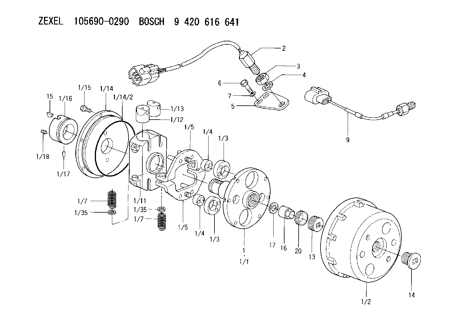
| 1. | [1] | 156990-3620 | AUTO;TIMING DEVICE |
| 1/1. | [1] | 156900-9522 | FLANGE BUSHING |
| 1/2. | [1] | 156901-9121 | TIMING-DEVICE HOUSING |
| 1/3. | [2] | 156904-0400 | ECCENTRIC DISC |
| 1/3. | [2] | 156904-0400 | ECCENTRIC DISC |
| 1/4. | [2] | 156904-0500 | ECCENTRIC DISC |
| 1/4. | [2] | 156904-0500 | ECCENTRIC DISC |
| 1/5. | [2] | 156907-3721 | PLATE |
| 1/5. | [2] | 156907-3721 | PLATE |
| 1/7. | [4] | 156908-6900 | COILED SPRING |
| 1/7. | [4] | 156908-6900 | COILED SPRING |
| 1/11. | [1] | 156905-1821 | CYLINDER |
| 1/12. | [2] | 156906-0201 | PUMP PLUNGER |
| 1/13. | [2] | 156906-0201 | PUMP PLUNGER |
| 1/14. | [1] | 156902-1722 | COVER |
| 1/14/2. | [1] | 139799-0300 | O-RING |
| 1/15. | [6] | 156913-3300 | BLEEDER SCREW |
| 1/16. | [1] | 156913-4820 | TIMING RING |
| 1/17. | [1] | 156911-0600 | BEARING PIN |
| 1/18. | [1] | 011004-0820 | SET OF NUTS |
| 1/35. | [4] | 156913-7300 | SHIM |
| 1/35. | [4] | 156913-7300 | SHIM |
| 2. | [1] | 479772-0300 | PULSE GENERATOR |
| 3. | [1] | 029201-6150 | UNION NUT |
| 4. | [1] | 139316-0000 | PLAIN WASHER |
| 5. | [1] | 156913-8300 | PLATE |
| 6. | [2] | 020018-2070 | BLEEDER SCREW |
| 7. | [2] | 014020-8140 | PLAIN WASHER |
| 9. | [1] | 479772-0420 | PULSE GENERATOR |
| 13. | [1] | 156914-7300 | CAPSULE |
| 14. | [1] | 156914-4521 | CAPSULE |
| 15. | [1] | 025804-1610 | WOODRUFF KEY |
| 16. | [1] | 131325-1800 | UNION NUT |
| 17. | [1] | 029321-4030 | LOCKING WASHER |
| 20. | [1] | 156914-7400 | FILLER PIECE |
Cross reference number
Zexel num
Bosch num
Firm num
Name
105690-0290
9 420 616 641
AUTO;TIMING DEVICE
K 14KN VARIABLE TIMER TIMER V/T TIMER
K 14KN VARIABLE TIMER TIMER V/T TIMER
Information:
Reversal of Crankcase
Gently lay the crankcase on its side, then turn the crankcase upside down.
Resting the crankcase with the oil pan on the bottom can cause the oil pan to crack.
Reversal of crankcaseRemoval of Oil Pan And Oil Pan Gasket
(1) Unscrew the oil pan mounting bolts, and detach the oil pan.(2) Remove the oil pan gasket.
Removal of oil pan and oil gasketRemoval of Oil Pump
Unscrew the oil pump set bolt, and pull out the oil pump.
Removal of oil pumpRemoval of Camshaft
(1) Position the camshaft gear so that the two lightening holes are on the top and bottom, then remove the thrust plate mounting bolts using the socket. (2) Pull out the camshaft from the crankcase.
Removal of camshaft
Be careful not to damage the cams and bearing sections on the camshaft.
Removal of Front Plate
Unscrew the front plate mounting bolts, and dismount the front plate (together with the injection pump) from the crankcase.
Removal of front platePistons, Connecting Rods, Crankshaft and Crankcase
When replacing the crankcase, remove all accessories (relief valve and others) carefully from the crankcase, and reinstall them on a new crankcase.Laying Crankcase on Its Side
Gently lay the crankcase on its side.
Laying crankcase on its sideMeasurement of Thrust Clearance on Big-End of Connecting Rod
(1) Measure the clearance between the big-end of each connecting rod and the crankshaft (end play) with feeler gages. (2) If the measured clearance exceeds the limit value, replace the connecting rod.
Measurement of thrust clearance on big-end of connecting rodWeight Difference Among Connecting Rod Assemblies
When replacing connecting rods, make sure that all connecting rods have the same weight rank mark.
Weight rank mark on connecting rodRemoval of Connecting Rod Caps
(1) On each connecting rod and cap, put a mark indicating its cylinder No.(2) Remove the connecting rod caps.(3) For each removed connecting rod bearing (lower half), indicate the piston No. from which it was removed and the upper/lower identification. Be careful not to damage the bearings. Arrange the removed bearings in such a way that they can be reinstalled in their original positions during reassembly.
Removal of connecting rod capPreparation For Removal of Pistons
If carbon deposits are present at the upper sections of the cylinders, remove the carbon deposits with sandpaper and a cloth to facilitate piston removal.
Preparation for removal of pistonRemoval of Pistons
(1) Turn the crankshaft to bring the piston to be removed to the top dead center.(2) Using the wooden handle of a hammer, push the connecting rod on the cap contacting surface to remove the piston and connecting rod assembly from the top side of the cylinder.
Removal of pistonRemoval of Piston Ring
Using the piston ring pliers, remove the piston rings
Removal of piston ringRemoval of Piston Pins
Removal of piston pin(1) Using the snap ring pliers, remove the snap rings.(2) Pull out the piston pin, and separate the piston from the connecting rod.(3) If the piston pin cannot be remove easily, heat the piston with a piston heater or in hot water.Reversal of Crankcase
Gently stand the crankcase so that the oil pan mounting side faces up.
Reversal of crankcaseMeasurement of
Have questions with 105690-0290?
Group cross 105690-0290 ZEXEL
Nissan-Diesel
Isuzu
Isuzu
Isuzu
Isuzu
105690-0290
9 420 616 641
AUTO;TIMING DEVICE