Information adjusting device
BOSCH
F 019 Z1F 985
f019z1f985
ZEXEL
159601-9220
1596019220
MITSUBISHI
ME756572
me756572
Rating:
Scheme ###:
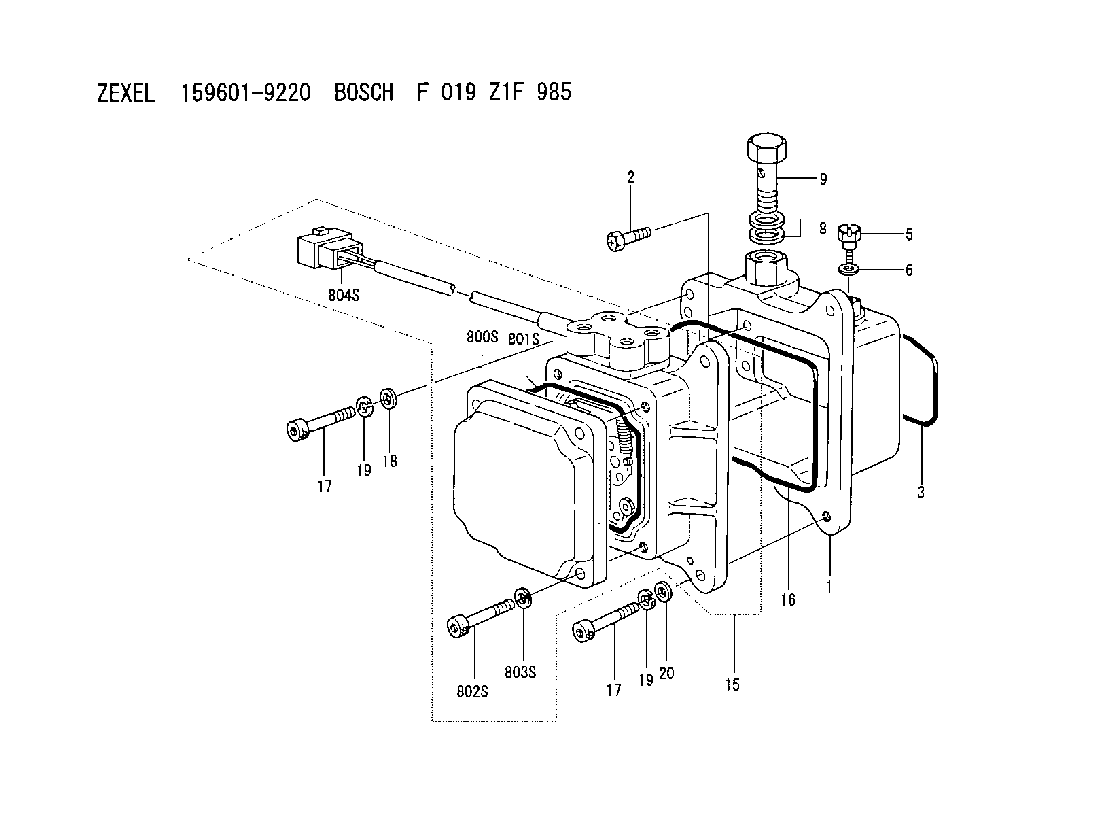
| 1. | [1] | 159598-3620 | DIAPHRAGM HOUSING |
| 2. | [6] | 159596-2800 | BLEEDER SCREW |
| 3. | [1] | 159610-4100 | SEAL RING |
| 5. | [1] | 131420-0400 | BLEEDER SCREW |
| 6. | [1] | 026506-1040 | GASKET D9.9&6.2T1 |
| 8. | [2] | 029341-4130 | GASKET D20&13.8T2* |
| 9. | [1] | 029731-4680 | EYE BOLT |
| 15. | [1] | 159605-7920 | ACTUATOR |
| 16. | [1] | 159610-4200 | SEAL RING |
| 17. | [4] | 010206-3040 | HEX-SOCKET-HEAD CAP SCREW M6P1L30 |
| 17. | [4] | 010206-3040 | HEX-SOCKET-HEAD CAP SCREW M6P1L30 |
| 18. | [1] | 139306-0400 | PLAIN WASHER |
| 19. | [4] | 029320-6010 | LOCKING WASHER |
| 19. | [4] | 029320-6010 | LOCKING WASHER |
| 20. | [3] | 159595-5700 | PLAIN WASHER |
| 800S. | [1] | 159595-8801 | COVER |
| 801S. | [1] | 159610-4300 | SEAL RING |
| 802S. | [4] | 010206-3040 | HEX-SOCKET-HEAD CAP SCREW M6P1L30 |
| 803S. | [4] | 029320-6010 | LOCKING WASHER |
| 804S. | [1] | 159910-6800 | PLUG HOUSING |
Include in #1:
108622-2382
as _
Cross reference number
Zexel num
Bosch num
Firm num
Name
159601-9220
F 019 Z1F 985
ME756572 MITSUBISHI
ADJUSTING DEVICE
A K 74HA ACTUATOR ASSY FUN ACT
A K 74HA ACTUATOR ASSY FUN ACT
Information:
Procedure
Illustration 1 g06220548
(1) TC Mark (Flywheel Housing)
(2) TC Mark (Flywheel)
Remove valve cover, and injector and rocker arm. Bring the piston of cylinder 4 to TDC.
Illustration 2 g06220554
(3) Dial Gauge
(4) Valve
(5) O-ring
Remove the #4 exhaust valve bridge arm and valve spring. Insert a small O-ring (5) so the valve does not fall into the cylinder.
Set dial gauge (3) on the tip of the valve (4).
Illustration 3 g06220569
(6) Tri - Square
(7) Flywheel Housing
(8) Flywheel
Illustration 4 g06220573
(7) Flywheel Housing
(8) Flywheel
(9) Reference Line
Turn the flywheel counterclockwise and measure the position where the tip of the valve is the highest.
Stop the flywheel at the position where the tip of the valve is the highest. Put a tri - square (6) on the flywheel housing (7) and the flywheel (8) and draw a reference line (9).Do not drop the valve (4) into the cylinder. When measuring the highest position of the tip of the valve, do not rotate the flywheel clockwise. If you go past the highest point of the valve, back up the flywheel slightly and measure the highest point of the valve. The reference line (9) indicates the TDC of the crankshaft.
Illustration 5 g06220579
Rotation Sensor Signal Interface Unit
Application: Use for reading rotation sensor signal.
(1) 9V Battery
(2) Switch
(3) 3-Terminal Regulator
(4) LED
(5) Clip (Red)
(6) Clip (Black)
(A) for Panasonic
(B) for Denso
(C) for Bosch cam angle
(D) for Bosch crank angle
((E)) Connector Side
(a) +9 V
(b) Signal
(c) GND
(d) +5 V
(e) Signal
(f) GND
Schematic to build Rotation Sensor Signal Interface.
Illustration 6 g06220581
(10) Rotation Sensor Signal Interface (Tool not available. Schematic to build tool available. Refer to Step 6.
(11) Tester
Illustration 7 g06220587
(12) Ground Terminal
(13) Output Terminal
(14) Crankshaft Position Sensor
Connect a connector of the rotation sensor signal interface unit (10) to the crankshaft position sensor (14). Connect each clip of the rotation sensor signal interface unit (10) to the same test lead color of the tester (11). Switch on the rotation sensor signal interface unit (10).
Illustration 8 g06220590
(15) Pulsar Gear
(16) 14th Tooth
(17) Missing Teeth
Turn the flywheel and make sure that the voltage of the crankshaft position sensor goes from 0→ 5 V or 5 → 0 V.
Rotate the flywheel and align the crankshaft position sensor to the part of the pulsar gear (15) that is missing teeth (17). The 14th tooth (16) from the missing teeth is standard.
Slowly turn flywheel counterclockwise and stop flywheel at the point where needle of the tester changes momentarily from 0 → 5 V, the 14th tooth.That point is where the crankshaft position sensor detects TDC.
Illustration 9 g06220608
(18) Crankshaft TDC
(19) Detection Point of Crankshaft Position Sensor TDC
Illustration 10 g06220612
(20) Interval
Set the tri - square (6) on the reference line (9) on the flywheel housing side and mark the detection point of crankshaft position sensor TDC (19) on the flywheel.
Measure the interval (20) between the crankshaft TDC (18) and the detection point of the crankshaft position sensor TDC (19).
Calculation of fuel injection timing correction 1.0 mm (0.039 in.): 0.321°.Corrected Angle = 0.321° X actual interval
Overwrite the injection timing correction value on the engine ecm registration website refer to REHS9707, "Registering Diesel Particulate Filter (DPF), Diesel Oxidation Catalyst (DOC),
Have questions with 159601-9220?
Group cross 159601-9220 ZEXEL
Mitsubishi
159601-9220
F 019 Z1F 985
ME756572
ADJUSTING DEVICE