Information adjusting device
BOSCH
F 019 Z2E 925
f019z2e925
ZEXEL
159601-2522
1596012522
HINO
227102340A
227102340a

Rating:
Scheme ###:
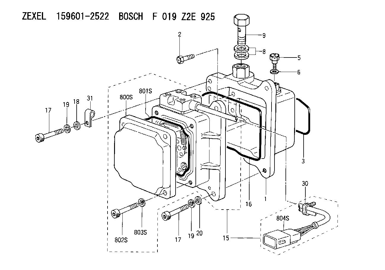
| 1. | [1] | 159598-2321 | DIAPHRAGM HOUSING |
| 2. | [4] | 159596-2800 | BLEEDER SCREW |
| 3. | [1] | 159610-1400 | SEAL RING |
| 5. | [1] | 131420-0400 | BLEEDER SCREW |
| 6. | [1] | 026506-1040 | GASKET D9.9&6.2T1 |
| 8. | [2] | 139514-0300 | GASKET |
| 9. | [1] | 029731-4680 | EYE BOLT |
| 15. | [1] | 159605-2722 | ACTUATOR |
| 16. | [1] | 159610-1300 | SEAL RING |
| 17. | [4] | 010206-3040 | HEX-SOCKET-HEAD CAP SCREW M6P1L30 |
| 17. | [4] | 010206-3040 | HEX-SOCKET-HEAD CAP SCREW M6P1L30 |
| 18. | [1] | 139306-0400 | PLAIN WASHER |
| 19. | [4] | 029320-6010 | LOCKING WASHER |
| 19. | [4] | 029320-6010 | LOCKING WASHER |
| 20. | [3] | 159595-5700 | PLAIN WASHER |
| 30. | [1] | 159911-1100 | CLAMPING BAND |
| 31. | [1] | 159597-1000 | CLAMPING BAND |
| 800S. | [1] | 159595-8801 | COVER |
| 801S. | [1] | 159610-1200 | SEAL RING |
| 802S. | [4] | 010206-3040 | HEX-SOCKET-HEAD CAP SCREW M6P1L30 |
| 803S. | [4] | 029320-6010 | LOCKING WASHER |
| 804S. | [1] | 159911-4500 | PLUG HOUSING |
Include in #1:
108622-3733
as _
Cross reference number
Zexel num
Bosch num
Firm num
Name
159601-2522
F 019 Z2E 925
227102340A HINO
ADJUSTING DEVICE
K 74HA ACTUATOR ASSY FUN ACT
K 74HA ACTUATOR ASSY FUN ACT
Information:
Safety Precautions
Make sure that you disconnect all power to the monitor before performing any of the procedures that follow.
Disconnect all electrical power from the monitor before removing components. Failure to disconnect the power could result in severe electrical shock or damage to the monitor. An electrical shock can cause severe personal injury or death.
Removing The Flat Panel Display
The monitor has 10 screws that secure the flat panel display to the chassis.In order to remove the flat panel display, perform the following procedure:
Remove the top cover of the monitor. Refer to Testing and Adjusting, "Cover - Remove" for details on removing the top cover.
Illustration 1 g00858319
Central Processing Unit (CPU) Card (1) Display Connector
Disconnect the video cable that is connected to the display connector (1) on the CPU card.
Illustration 2 g00858320
(2) Power Supply (3) Touchscreen Controller Board (4) Pin 1 on the touchscreen cable connector
If the unit is equipped with a touchscreen, remove the back cover of the monitor. Refer to Testing and Adjusting, "Cover - Remove" for details on removing the back cover.Disconnect the touchscreen cable (flexible cable) from the touchscreen controller board (3). The touchscreen controller board (3) is attached to the outside of the power supply (2) .
Illustration 3 g00858321
10 Screws
Remove the 10 screws that secure the flat panel display to the chassis of the monitor.
Illustration 4 g00858322
(5) Video Cable (6) Backlight Power Supply (7) Indicator Board (8) Backlight TubesNote: This illustration shows the 264 mm (10.4 inch) version. The backlight power supply board (6) on the 307 mm (12.1 inch) version is mounted on a separate detachable bracket. The backlight power supply board is not mounted on the back of the display.
Carefully pull the flat panel display away from the chassis and disconnect the following connectors from the flat panel display:
Indicator connector from the indicator board (7)
Power cable that is attached to the backlight power supply (6) Replacing The Backlight Tubes
The backlight assembly contains two backlight tubes (8), which must be replaced. The replacement tubes are 203-7814 Boards .In order to replace the backlight tubes (8), perform the following procedure:
Disconnect the backlight tube connectors from the backlight power supply (6) .
Remove the two screws that are holding each backlight tube (8) in place.
Slide the tube to the left and gently pull the tube out of the assembly.
Insert the replacement backlight tube into the slot. Slide the tube to the right until the holes for the screws are aligned. Replace the screws.
Reattach the backlight tube connectors to the backlight power supply (6) .
Reattach the indicator connector to the indicator board (7) and the power cable to the backlight controller board.
Reattach the display cable to the CPU card. Attach the touchscreen cable to the touchscreen controller board (3) .
Reattach the display assembly to the unit. Use the 10 screws.
Replace the top cover of the unit. Replace the back cover of the unit.
Have questions with 159601-2522?
Group cross 159601-2522 ZEXEL
Hino
159601-2522
F 019 Z2E 925
227102340A
ADJUSTING DEVICE