Information adjusting device
BOSCH
F 019 Z3E 631
f019z3e631
ZEXEL
159600-9320
1596009320
MITSUBISHI
ME742680
me742680
Rating:
Scheme ###:
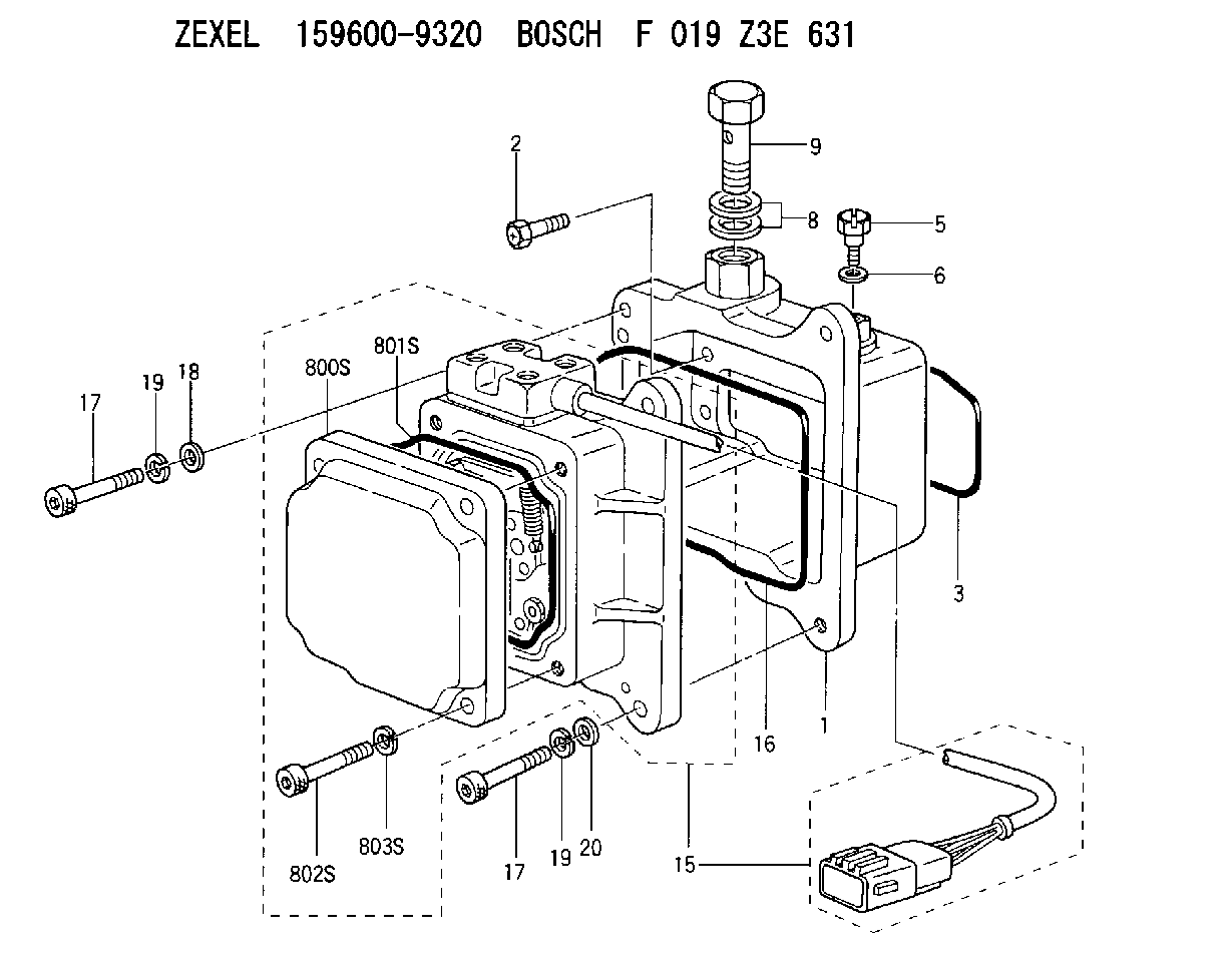
| 1. | [1] | 159595-3821 | DIAPHRAGM HOUSING |
| 2. | [4] | 159596-2800 | BLEEDER SCREW |
| 3. | [1] | 159595-9800 | SEAL RING |
| 5. | [1] | 131420-0400 | BLEEDER SCREW |
| 6. | [1] | 026506-1040 | GASKET D9.9&6.2T1 |
| 8. | [2] | 029341-4130 | GASKET D20&13.8T2* |
| 9. | [1] | 029731-4680 | EYE BOLT |
| 15. | [1] | 159604-9621 | ACTUATOR |
| 16. | [1] | 159596-5800 | SEAL RING |
| 17. | [4] | 010206-3040 | HEX-SOCKET-HEAD CAP SCREW M6P1L30 |
| 17. | [4] | 010206-3040 | HEX-SOCKET-HEAD CAP SCREW M6P1L30 |
| 18. | [1] | 139306-0400 | PLAIN WASHER |
| 19. | [4] | 029320-6010 | LOCKING WASHER |
| 19. | [4] | 029320-6010 | LOCKING WASHER |
| 20. | [3] | 159595-5700 | PLAIN WASHER |
| 800S. | [1] | 159595-8801 | COVER |
| 801S. | [1] | 159596-1400 | SEAL RING |
| 802S. | [4] | 010206-3040 | HEX-SOCKET-HEAD CAP SCREW M6P1L30 |
| 803S. | [4] | 029320-6010 | LOCKING WASHER |
Include in #1:
108622-2251
as _
Cross reference number
Zexel num
Bosch num
Firm num
Name
Information:
Test Procedure
System Operation
The engine speed switch accepts a signal from the magnetic pickup. The magnetic pickup is mounted on the engine. The speed switch determines the engine speed from the signal. The speed switch provides contacts for the following list of conditions:
Crank Terminate
Engine Oil Step Pressure
Engine Overspeed
Nine Second Time Delay
Illustration 1 g00562933
Diagram of the engine speed switchFunctional Test
Check the electrical connectors and check the wiring.
Bodily contact with electrical potential can cause bodily injury or death.To avoid the possibility of injury or death, ensure that the main power supply has been disconnected before performing any maintenance or removing any modules.
Disconnect the power supply.
Check the electrical connectors and check the wiring for damage or bad connections.
Verify that all modules are properly seated.
Verify the status of the LED on the SLC 5/04.The results of the preceding procedure are in the following list:
All of the components are fully installed. All of the components are free of corrosion. All of the components are free of damage. All of the modules are properly seated. Proceed to 2.
The components are not fully installed. The components are not free of corrosion. The components are damaged. All of the modules are not properly seated. Repair the component. Verify that the repair resolves the problem. STOP.
Verify that the engine speed switch is receiving power.
Bodily contact with electrical potential can cause bodily injury or death.To avoid the possibility of injury or death, ensure that the main power supply has been disconnected before performing any maintenance or removing any modules.
Measure the voltage on the junction box terminal strip. Measure the voltage between the following terminals: junction box terminal 6 and junction box terminal 5. The voltage should be 24 2 VDC between the junction box terminals.The results of the preceding procedure are in the following list:
The voltage is in the range. Proceed to 3.
The voltage is not in the range. Refer to Troubleshooting, "System Power". Stop.
Check the magnetic pickup.
Measure the voltage on the junction box terminal strip. Measure the voltage between the following terminals: junction box terminal 4 and junction box terminal 3. The voltage should be 5 2 VAC between the junction box terminals.The results of the preceding procedure are in the following list:
The voltage is in the range. Proceed to 4.
The voltage is not in the range. Refer to Troubleshooting, "System Power". Stop.
Test the contact for the engine speed switch.
Bodily contact with electrical potential can cause bodily injury or death.To avoid the possibility of injury or death, ensure that the main power supply has been disconnected before performing any maintenance or removing any modules.
Press the overspeed reset. This de-energizes the contact for the overspeed switch.
Measure the resistance on the junction box terminal strip. Measure the resistance between the following terminals: junction box terminal 11 and junction box terminal 12. The resistance should be zero ohms between the junction box terminals.The results of the preceding procedure are in the following list:
The resistance is good. Stop.
The resistance is not good. Replace the engine speed switch. Stop.