Information adjusting device
BOSCH
9 421 620 899
9421620899
ZEXEL
159600-9121
1596009121
HINO
227101412A
227101412a

Rating:
Scheme ###:
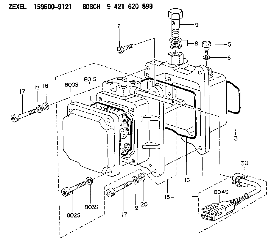
| 1. | [1] | 159598-2321 | DIAPHRAGM HOUSING |
| 2. | [4] | 159596-2800 | BLEEDER SCREW |
| 3. | [1] | 159595-9800 | SEAL RING |
| 5. | [1] | 131420-0400 | BLEEDER SCREW |
| 6. | [1] | 026506-1040 | GASKET D9.9&6.2T1 |
| 8. | [2] | 139514-0300 | GASKET |
| 9. | [1] | 029731-4680 | EYE BOLT |
| 15. | [1] | 159604-9421 | ACTUATOR |
| 16. | [1] | 159596-5800 | SEAL RING |
| 17. | [4] | 010206-3040 | HEX-SOCKET-HEAD CAP SCREW M6P1L30 |
| 17. | [4] | 010206-3040 | HEX-SOCKET-HEAD CAP SCREW M6P1L30 |
| 18. | [1] | 139306-0400 | PLAIN WASHER |
| 19. | [4] | 029320-6010 | LOCKING WASHER |
| 19. | [4] | 029320-6010 | LOCKING WASHER |
| 20. | [3] | 159595-5700 | PLAIN WASHER |
| 30. | [1] | 159911-1100 | CLAMPING BAND |
| 800S. | [1] | 159595-8801 | COVER |
| 801S. | [1] | 159596-1400 | SEAL RING |
| 802S. | [4] | 010206-3040 | HEX-SOCKET-HEAD CAP SCREW M6P1L30 |
| 803S. | [4] | 029320-6010 | LOCKING WASHER |
| 804S. | [1] | 159911-4500 | PLUG HOUSING |
Cross reference number
Zexel num
Bosch num
Firm num
Name
Information:
Test Procedure
System Operation
The SLC 5/04 diagnostic indicators are located on the front of the following components: Power Supply, CPU and I/O Modules.The diagnostic indicators help trace the source of the fault. Faults can be found in the following components: Input devices, Output devices, Wiring and The controller.The green "DH+" LED is flashing. There are no active nodes on the network.The red "DH+" LED is flashing. There are duplicate active nodes on the link with the same address.The red "FLT" LED is flashing during operation. The processor detects a major fault. The fault is in the processor expansion chassis or the fault is in the memory.
Illustration 1 g00563551
Diagram of the LED indicators
Illustration 2 g00562937
Functional Test
Check the electrical connectors and check the wiring.
Bodily contact with electrical potential can cause bodily injury or death.To avoid the possibility of injury or death, ensure that the main power supply has been disconnected before performing any maintenance or removing any modules.
Disconnect the power supply.
Check the electrical connectors and check the wiring for damage or bad connections.
Verify that all modules are properly seated.
Verify the status of the LED on the SLC 5/04.The results of the preceding procedure are in the following list:
All of the components are fully installed. All of the components are free of corrosion. All of the components are free of damage. All of the modules are properly seated. Proceed to 2.
The components are not fully installed. The components are not free of corrosion. The components are damaged. All of the modules are not properly seated. Repair the component. Verify that the repair resolves the problem. STOP.
Check the communication parameters of the customer supplied devices.
Check the communication parameter of the programmer.The results of the preceding procedure are in the following list:
The programmer address and the processor address are different. Proceed to 3.
The programmer address and the processor address are not different. Set the addresses. Verify that the repair resolves the problem. Stop.
Change the baud rate.
Change the baud rate of the programmer and change the baud rate of the processor.
Increase the maximum node address.Note: The default baud rate is 57,600. The default node address is one.The results of the preceding procedure are in the following list:
No errors are displayed on the LED indicators. Stop.
Errors are displayed on the LED indicators. Proceed to 4.
Check line voltage.
Measure the line voltage at the terminals.
Verify the voltage of the power supply. The power supply voltage should be measured between 21.0 VDC and 28.0 VDC.The results of the preceding procedure are in the following list:
The line voltage is in the range. Replace the processor. Verify that the repair solves the problem. Refer to Maintenance Procedure, "Processor - Replace".
The line voltage is out of the range. Refer to Troubleshooting, "System Power". Stop.