Information adjusting device
BOSCH
9 421 613 644
9421613644
ZEXEL
159600-8620
1596008620
MITSUBISHI
ME742896
me742896

Rating:
Scheme ###:
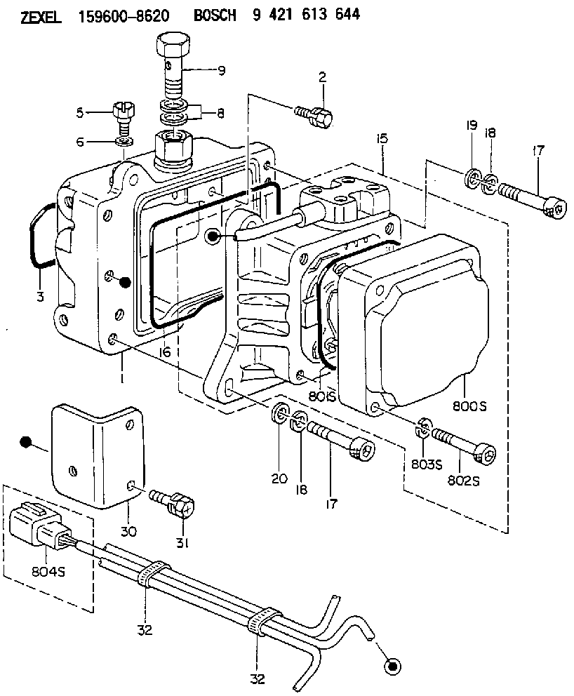
| 1. | [1] | 159598-2623 | DIAPHRAGM HOUSING |
| 2. | [4] | 159596-2800 | BLEEDER SCREW |
| 3. | [1] | 159596-1200 | SEAL RING |
| 5. | [1] | 131420-0400 | BLEEDER SCREW |
| 6. | [1] | 026506-1040 | GASKET |
| 8. | [2] | 029341-4130 | GASKET |
| 9. | [1] | 139814-0900 | EYE BOLT |
| 15. | [1] | 159604-9020 | ACTUATOR |
| 16. | [1] | 159596-1300 | SEAL RING |
| 17. | [4] | 010206-3040 | HEX-SOCKET-HEAD CAP SCREW |
| 17. | [4] | 010206-3040 | HEX-SOCKET-HEAD CAP SCREW |
| 18. | [4] | 029320-6010 | LOCKING WASHER |
| 18. | [4] | 029320-6010 | LOCKING WASHER |
| 19. | [1] | 139306-0400 | PLAIN WASHER |
| 20. | [3] | 159595-5700 | PLAIN WASHER |
| 30. | [1] | 159597-6700 | BRACKET |
| 31. | [2] | 020106-1440 | BLEEDER SCREW |
| 32. | [2] | 159911-1100 | CLAMPING BAND |
| 32. | [2] | 159911-1100 | CLAMPING BAND |
| 800S. | [1] | 159595-9201 | COVER |
| 801S. | [1] | 159596-1400 | SEAL RING |
| 802S. | [4] | 010206-3040 | HEX-SOCKET-HEAD CAP SCREW |
| 803S. | [4] | 029320-6010 | LOCKING WASHER |
| 804S. | [1] | 159910-6800 | PLUG HOUSING |
Cross reference number
Zexel num
Bosch num
Firm num
Name
Information:
Self-Diagnostics
The electronic system has self-diagnostic capabilities. When a problem is detected, a fault indicator is illuminated on the front of the module. A panel of indicators is also located on the MECP.Module Fault Indicators
A fault should be immediately serviced. A fault indicator is illuminated when a problem exists. When the PLC has an active fault, find the appropriate procedure in the troubleshooting section.Operating Information that is Stored in the Programmable Logic Controller
The SLC 5/04 uses a battery in order to provide backup power to the C-MOS RAM.Programmable Logic Controller Chassis or Rack
The PLC chassis contains the following components:
Power Supply
CPU Module
Input Modules
Output Modules
User Defined ModulesThe system uses the Allen-Bradley SLC 500 series of PLC.Central Processing Unit
Illustration 1 g00562937
The SLC 5/04 processor includes a three-position keyswitch on the front panel. The key switches the system from the following three modes of operation: RUN, PROGRAM and REMOTEThe key can be removed in each of the three positions. The mode changes when the position of the key is switched from the RUN position. Do not substitute the keyswitch for a master control relay. Do not substitute the keyswitch for an emergency stop switch.RUN Position
The RUN position places the processor in the run mode. The processor conducts the following functions:
The processor scans the ladder program.
The processor executes the ladder program.
The processor monitors input devices.
The processor energizes the output devices.
The processor acts on the enabled I/O forces.You can only change the processor's mode with the keyswitch. Revising of the program cannot be performed when you are on-line."PROG" Position
The Program position places the processor in the program mode. The processor does not scan the program and the processor does not execute the program. The controller's outputs are de-energized.You can only change the processor's mode with the keyswitch. Revising of the program can be performed when you are on-line.When the keyswitch is in the program position, a qualified technician can use the programmer interface device in order to change the processor's mode.Remote Position
The remote position places the processor in the remote mode. You can only change the processor's mode with the keyswitch. Revising of the program can be performed when you are on-line.When the keyswitch is in the remote position, a qualified technician can use the programmer interface device in order to change the processor's mode.Processor's Fault Indicators
A fault should be immediately serviced. A fault indicator is illuminated when a problem exists. When the PLC has an active fault, find the appropriate procedure in the troubleshooting section.The Processor's Indicators
Six LED indicators are on the front of the CPU module. The indicators show the operating status of your processor. The indicators have the labels that are in the following list:"RUN", "FLT", "BATT", "FORCE", "DH+" and "RS232"Thermocouple Module
The thermocouple module contains diagnostic features that can identify sources of problems. The problems may occur during power up. The problems may occur during normal operation. Each channel can receive a signal from the sensors or from the analog input devices.
Illustration 2 g00562940
LED indicatorsResistance Temperature Detector Module
The RTD module contains diagnostic features that