Information adjusting device
BOSCH
9 421 616 040
9421616040
ZEXEL
159600-7720
1596007720
MITSUBISHI
ME742228
me742228

Rating:
Scheme ###:
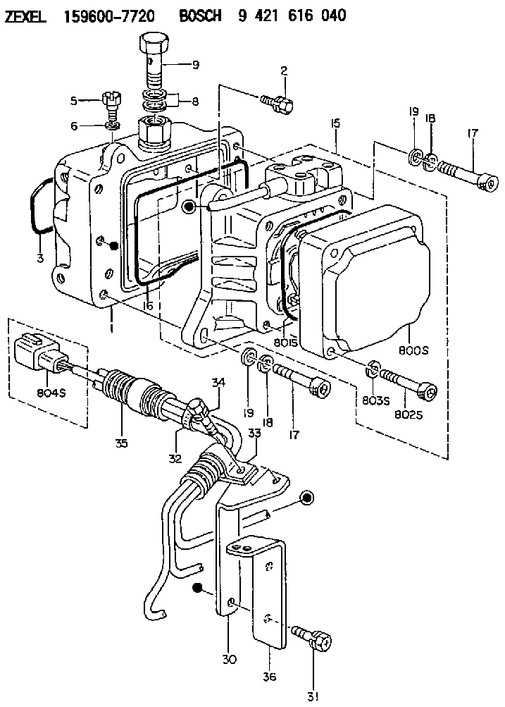
| 1. | [1] | 159598-2721 | DIAPHRAGM HOUSING |
| 2. | [4] | 159596-2800 | BLEEDER SCREW |
| 3. | [1] | 159596-1200 | SEAL RING |
| 5. | [1] | 131420-0400 | BLEEDER SCREW |
| 6. | [1] | 026506-1040 | GASKET D9.9&6.2T1 |
| 8. | [2] | 029341-4130 | GASKET D20&13.8T2* |
| 9. | [1] | 139814-0900 | EYE BOLT |
| 15. | [1] | 159604-8120 | ACTUATOR |
| 16. | [1] | 159596-1300 | SEAL RING |
| 17. | [4] | 010206-3040 | HEX-SOCKET-HEAD CAP SCREW M6P1L30 |
| 17. | [4] | 010206-3040 | HEX-SOCKET-HEAD CAP SCREW M6P1L30 |
| 18. | [4] | 029320-6010 | LOCKING WASHER |
| 18. | [4] | 029320-6010 | LOCKING WASHER |
| 19. | [4] | 139306-0400 | PLAIN WASHER |
| 19. | [4] | 139306-0400 | PLAIN WASHER |
| 30. | [1] | 159597-6901 | BRACKET |
| 31. | [2] | 020106-1440 | BLEEDER SCREW M6P1.0L14 |
| 32. | [3] | 159911-1100 | CLAMPING BAND |
| 33. | [1] | 159597-5000 | CLAMPING BAND |
| 34. | [1] | 020106-0840 | BLEEDER SCREW |
| 35. | [1] | 159900-7100 | TUBE |
| 36. | [1] | 159597-6800 | BRACKET |
| 800S. | [1] | 159595-9201 | COVER |
| 801S. | [1] | 159596-1400 | SEAL RING |
| 802S. | [4] | 010206-3040 | HEX-SOCKET-HEAD CAP SCREW M6P1L30 |
| 803S. | [4] | 029320-6010 | LOCKING WASHER |
| 804S. | [1] | 159910-6800 | PLUG HOUSING |
Cross reference number
Zexel num
Bosch num
Firm num
Name
Information:
Illustration 1 g00565418
4W-8471 Time Delay Relay
Use a 6V-7070 Digital Multimeter, a stopwatch, and a battery (8 volts to 40 volts) for this test.
Connect the positive lead of the voltage source to terminal (TD-4) of the time delay relay. Connect the negative lead to terminal (TD-3). If the test is done on an engine, the start/stop switch must be in the STOP position in order to power terminal (TD-6). All connections must be maintained until the tests are completed.
Use the multimeter to determine continuity. Compare the measurements to the following table.
Table 1
Terminals Relay Position
5-6 Closed
6-7 Open
Connect the positive lead of the voltage source to terminal (TD-1). If the time delay relay is tested on the engine do not leave the voltage source hooked to terminal (TD-1) for more than 60 seconds. The fuel shutoff solenoid will be energized. Use the multimeter to determine continuity. Compare the measurements to the following table.
Table 2
Terminals Relay Position
5-6 Open
6-7 Closed
Remove the positive lead of the voltage source from terminal (TD-1). Use the stopwatch to measure the time that is needed for the position of the relay to change. Use the multimeter to determine continuity. Compare the measurements to the following table.
Table 3
Terminals Delay Time of Relay Position
0 to 60 seconds 80 seconds or more
5-6 Open Closed
6-7 Closed Open Note: If a jumper is normally installed across terminals (TD-2) and (TD-3), the jumper must be removed before performing Step 5.
Connect the positive lead of the voltage source to terminal (TD-2). If the time delay relay is tested on the engine, do not leave the voltage source on terminal (TD-2) for more than 60 seconds. The fuel shutoff solenoid will be energized. Use the stopwatch to measure the time that is needed for the position of the relay to change. Use the multimeter to determine continuity. Compare the measurements to the following table.
Table 4
Terminals Delay Time of Relay Position
0 to 8 seconds 10 seconds or more
5-6 Closed Open
6-7 Open Closed
Remove the positive lead of the voltage source from terminal (TD-1). Use the stopwatch to measure the time that is needed for the position of the relay to change. Use the multimeter to determine continuity. Compare the measurements to the following table.
Table 5
Terminals Delay Time of Relay Position
0 to 60 seconds 80 seconds or more
5-6 Open Closed
6-7 Closed Open
Remove the voltage source from terminal (TD-4). Use the multimeter to determine continuity. Compare the measurements to the following table.
Table 6
Terminals Relay Position
5-6 Closed
6-7 Open