Information adjusting device
BOSCH
9 421 613 635
9421613635
ZEXEL
159600-3822
1596003822
MITSUBISHI
ME741722
me741722
Rating:
Scheme ###:
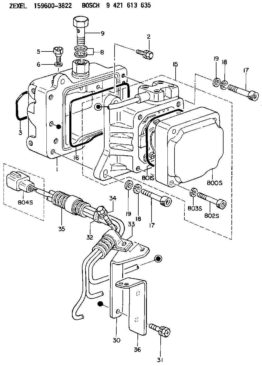
| 1. | [1] | 159598-2721 | DIAPHRAGM HOUSING |
| 2. | [4] | 159596-2800 | BLEEDER SCREW |
| 3. | [1] | 159596-1200 | SEAL RING |
| 5. | [1] | 131420-0400 | BLEEDER SCREW |
| 6. | [1] | 026506-1040 | GASKET |
| 8. | [2] | 029341-4130 | GASKET |
| 9. | [1] | 139814-0900 | EYE BOLT |
| 15. | [1] | 159604-5620 | ACTUATOR |
| 16. | [1] | 159596-1300 | SEAL RING |
| 17. | [4] | 010206-3040 | HEX-SOCKET-HEAD CAP SCREW |
| 17. | [4] | 010206-3040 | HEX-SOCKET-HEAD CAP SCREW |
| 18. | [4] | 029320-6010 | LOCKING WASHER |
| 18. | [4] | 029320-6010 | LOCKING WASHER |
| 19. | [4] | 139306-0400 | PLAIN WASHER |
| 19. | [4] | 139306-0400 | PLAIN WASHER |
| 30. | [1] | 159597-6901 | BRACKET |
| 31. | [2] | 020106-1440 | BLEEDER SCREW |
| 32. | [4] | 159911-1100 | CLAMPING BAND |
| 33. | [1] | 159597-5000 | CLAMPING BAND |
| 34. | [1] | 020106-0840 | BLEEDER SCREW |
| 35. | [1] | 159900-7100 | TUBE |
| 36. | [1] | 159597-6800 | BRACKET |
| 800S. | [1] | 159595-9201 | COVER |
| 801S. | [1] | 159596-1400 | SEAL RING |
| 802S. | [4] | 010206-3040 | HEX-SOCKET-HEAD CAP SCREW |
| 803S. | [4] | 029320-6010 | LOCKING WASHER |
| 804S. | [1] | 159910-6800 | PLUG HOUSING |
Include in #1:
107691-2373
as _
Cross reference number
Zexel num
Bosch num
Firm num
Name
Information:
Image1.1.1
Image1.1.2
Image1.1.3
Image1.1.4
Image1.1.5
Image1.1.6
Image1.1.7
Image1.1.8
Image1.1.9
PROCEDURES FOR DPF MODULE REWORK
PROCEDURE ( A ) See Image 1.2.1
Butt weld ring flush to retainer ring on the inlet assembly in 4 spots.
Fillet weld (3 mm weld size) 4 tabs (at 0, 90,180 and 270 degrees.
PROCEDURE ( B ) See Image 1.2.2
Butt weld ring flush to retainer ring on the inlet assembly in 4 spots.
Fillet weld (3 mm weld size) 4 tabs (at 0, 90,180 and 270 degrees.
PROCEDURE ( C ) See Image 1.2.3
Butt weld ring flush to retainer ring on the inlet assembly in 4 spots.
Fillet weld (3 mm weld size) 4 tabs (at 0, 90,180 and 270 degrees.
PROCEDURE ( D ) See Image 1.2.4
Butt weld ring flush to retainer ring on the inlet assembly in 4 spots.
Fillet weld (3 mm weld size) 4 tabs (at 0, 90,180 and 270 degrees.
PROCEDURE ( E ) See Image 1.2.5
Butt weld ring flush to retainer ring on inlet assembly in 4 spots.
Fillet weld 2 pins (at 0 and 180 degree orientation) to outlet side of DPF's 300 mm from each other.
Drill 5/8" holes in the outlet assembly flanges 300 mm from each other.
Place tube flush to the flange inside this hole and weld to outlet assembly.
PROCEDURE ( F ) See Image 1.2.6
Position plates (at 0 and 180 degree orientation) to outlet side of the DPF flange.
Allow plates to extend ( minimum 1/4 inch ) past outer edge. Using slots in plates
weld into place.
PROCEDURE ( G ) See Image 1.2.7
Fillet weld (3 mm weld size) 2 pins (at 0 and 180 degree orientation) to outlet side of DPF 260 mm from each other.
Drill a 5/8" hole in the outlet assembly flange 260 mm from each other 13 mm deep.
Place tube flush to the flange inside this hole and weld to outlet assembly.
PROCEDURE ( H ) See Image 1.2.8
Fillet weld 2 pins (at 0 and 180 degree orientation) to outlet side of both DPF's 300 mm from each other.
Drill 5/8" holes in the outlet assembly flanges 300 mm from each other 13 mm deep.
Place tubes flush to the flange inside this hole and weld to outlet assembly.
PROCEDURE ( I ) See Image 1.2.9 and Image 1.2.10
Remove the clamp and gasket from DPF inlet side.
Mate inlet flange to DPF without gasket or clamp.
Tack weld in place.
Apply a continuous weld to the inlet flange/DPF seam.
Image1.2.1
Image1.2.2
Image1.2.3
Image1.2.4
Image1.2.5
Image1.2.6
Image1.2.7
Image1.2.8
Image1.2.9
Image1.2.10
Filter Module Cross Reference Guide See Image 1.3.1.
Image1.3.1