Information adjusting device
BOSCH
9 421 614 615
9421614615
ZEXEL
159600-2820
1596002820
HINO
227101470A
227101470a
Rating:
Scheme ###:
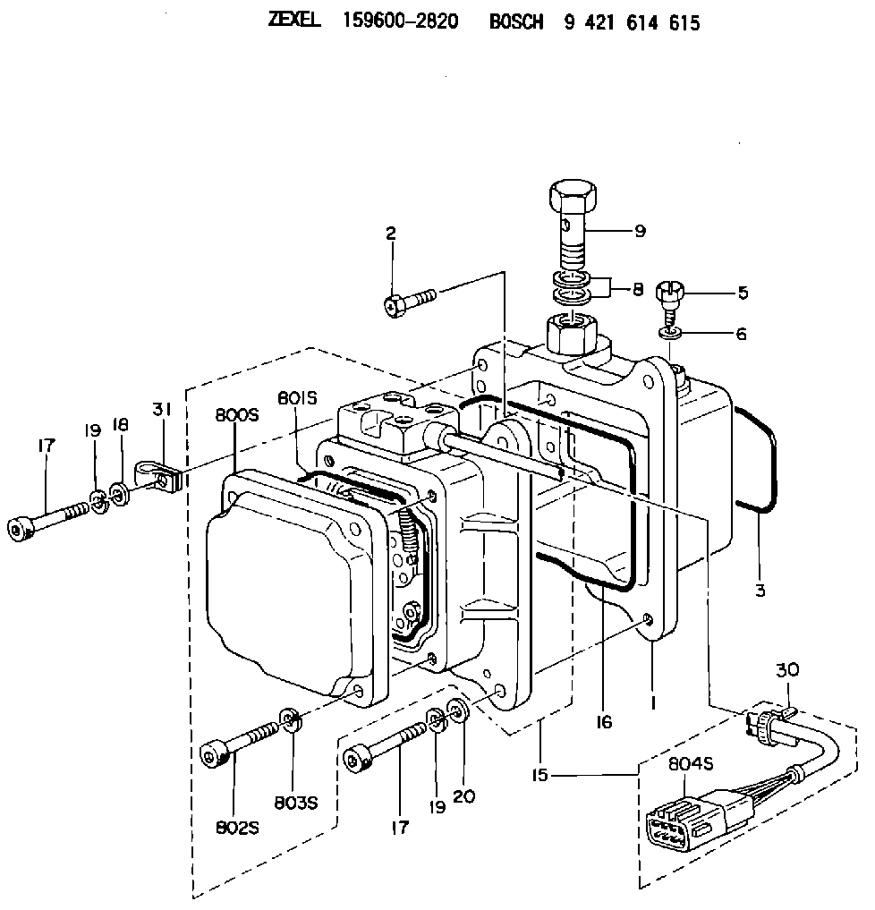
| 1. | [1] | 159595-3821 | DIAPHRAGM HOUSING |
| 2. | [4] | 159596-2800 | BLEEDER SCREW |
| 3. | [1] | 159595-9800 | SEAL RING |
| 5. | [1] | 131420-0400 | BLEEDER SCREW |
| 6. | [1] | 026506-1040 | GASKET D9.9&6.2T1 |
| 8. | [2] | 139514-0300 | GASKET |
| 9. | [1] | 029731-4680 | EYE BOLT |
| 15. | [1] | 159604-4220 | ACTUATOR |
| 16. | [1] | 159596-5800 | SEAL RING |
| 17. | [4] | 010206-3040 | HEX-SOCKET-HEAD CAP SCREW M6P1L30 |
| 17. | [4] | 010206-3040 | HEX-SOCKET-HEAD CAP SCREW M6P1L30 |
| 18. | [1] | 139306-0400 | PLAIN WASHER |
| 19. | [4] | 029320-6010 | LOCKING WASHER |
| 19. | [4] | 029320-6010 | LOCKING WASHER |
| 20. | [3] | 159595-5700 | PLAIN WASHER |
| 30. | [2] | 159911-1100 | CLAMPING BAND |
| 31. | [1] | 159597-1000 | CLAMPING BAND |
| 800S. | [1] | 159595-8801 | COVER |
| 801S. | [1] | 159596-1400 | SEAL RING |
| 802S. | [4] | 010206-3040 | HEX-SOCKET-HEAD CAP SCREW M6P1L30 |
| 803S. | [4] | 029320-6010 | LOCKING WASHER |
| 804S. | [1] | 159911-4500 | PLUG HOUSING |
Include in #1:
108822-3040
as _
Cross reference number
Zexel num
Bosch num
Firm num
Name
159600-2820
9 421 614 615
227101470A HINO
ADJUSTING DEVICE
K 74HA ACTUATOR ASSY FUN ACT
K 74HA ACTUATOR ASSY FUN ACT
Information:
Battery
Never disconnect any charging unit circuit or battery circuit cable from battery when the charging unit is operated. A spark can cause an explosion from the flammable vapor mixture of hydrogen and oxygen that is released from the electrolyte through the battery outlets. Injury to personnel can be the result.
Before any testing is done on the electrical system, the batteries should be checked for good connections and must be at least 75 percent (1.225 Sp Gr) fully charged.The battery circuit is an electrical load on the charging unit. The load is variable because of the condition of the charge in the battery. Damage to the charging unit will result if the connections (either positive or negative) between the battery and charging unit are broken while the charging unit is in operation. This is because the battery load is lost and there is an increase in charging voltage. High voltage will damage, not only the charging unit, but also the regulator and other electrical components.Use the 4C4911 Battery Load Tester to load test a battery that does not hold a charge when in use. Refer to Operating Manual, SEHS9249 for more detailed instructions on use of the 4C4911 Battery Load Tester. See Special Instruction, SEHS7633 for the correct procedure and specifications to use when testing batteries.Charging System
The condition of charge in the battery at each regular inspection will show if the charging system operates correctly. An adjustment is necessary when the battery is constantly in a low condition of charge or a large amount of water is needed (more than one ounce of water per cell per week or per every 100 service hours).When it is possible, make a test of the charging unit and voltage regulator on the engine, and use wiring and components that are a permanent part of the system. Off-engine (bench) testing will give a test of the charging unit and voltage regulator operation. This testing will give an indication of needed repair. After repairs are made, again make a test to give proof that the units are repaired to their original condition of operation.To check for correct output of the alternator, see the Specifications module.For complete service information, refer to Service Manual Module, SENR3862, Delco Remy 27-SI Series Alternators. This module is part of REG00636 Service Manual.Before the start of on-engine testing, the charging system and battery must be checked as shown in the Steps that follow:1. Battery must be at least 75 percent (1.225 Sp.Gr.) fully charged and held tightly in place. The Battery holder must not put too much stress on the battery.2. Cables between the battery, starter and engine ground must be the correct size. Wires and cables must be free of corrosion and have cable support clamps to prevent stress on battery connections (terminals).3. Leads, junctions, switches, and panel instruments that have direct relation to the charging circuit must give correct circuit control.4. Inspect the drive components for the charging unit to be sure they are free of grease and
Have questions with 159600-2820?
Group cross 159600-2820 ZEXEL
Hino
159600-2820
9 421 614 615
227101470A
ADJUSTING DEVICE