Information adjusting device
BOSCH
9 421 616 029
9421616029
ZEXEL
159600-1120
1596001120
HINO
227101351A
227101351a
Rating:
Scheme ###:
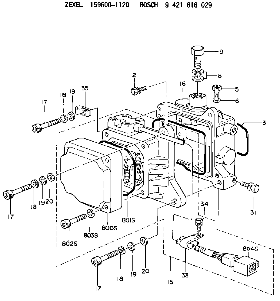
| 1. | [1] | 159595-8521 | DIAPHRAGM HOUSING |
| 2. | [4] | 159596-2800 | BLEEDER SCREW |
| 3. | [1] | 159596-1200 | SEAL RING |
| 5. | [1] | 131420-0400 | BLEEDER SCREW |
| 6. | [1] | 026506-1040 | GASKET D9.9&6.2T1 |
| 8. | [2] | 139514-0300 | GASKET |
| 9. | [1] | 029731-4680 | EYE BOLT |
| 15. | [1] | 159604-2421 | ACTUATOR |
| 16. | [1] | 159596-1300 | SEAL RING |
| 17. | [4] | 010206-3040 | HEX-SOCKET-HEAD CAP SCREW M6P1L30 |
| 17. | [4] | 010206-3040 | HEX-SOCKET-HEAD CAP SCREW M6P1L30 |
| 17. | [4] | 010206-3040 | HEX-SOCKET-HEAD CAP SCREW M6P1L30 |
| 18. | [4] | 029320-6010 | LOCKING WASHER |
| 18. | [4] | 029320-6010 | LOCKING WASHER |
| 18. | [4] | 029320-6010 | LOCKING WASHER |
| 19. | [1] | 139306-0400 | PLAIN WASHER |
| 19. | [1] | 139306-0400 | PLAIN WASHER |
| 19. | [1] | 139306-0400 | PLAIN WASHER |
| 20. | [3] | 159595-5700 | PLAIN WASHER |
| 20. | [3] | 159595-5700 | PLAIN WASHER |
| 31. | [2] | 020006-1440 | BLEEDER SCREW M6P1L14 |
| 33. | [1] | 159597-5100 | CLAMPING BAND |
| 34. | [1] | 020146-1240 | BLEEDER SCREW M6P1.0L12 |
| 35. | [1] | 159597-5100 | CLAMPING BAND |
| 800S. | [1] | 159595-8801 | COVER |
| 801S. | [1] | 159596-1400 | SEAL RING |
| 802S. | [4] | 010206-3040 | HEX-SOCKET-HEAD CAP SCREW M6P1L30 |
| 803S. | [4] | 029320-6010 | LOCKING WASHER |
| 804S. | [1] | 159911-4500 | PLUG HOUSING |
Cross reference number
Zexel num
Bosch num
Firm num
Name
159600-1120
9 421 616 029
227101351A HINO
ADJUSTING DEVICE
K 74HA ACTUATOR ASSY FUN ACT
K 74HA ACTUATOR ASSY FUN ACT
Information:
3. Turn the engine to the top center (TC) compression stroke for the No. 1 piston.4. Remove bolts (1), cover assembly (2) and the gasket from the front housing. 5. Remove two bolts (3). Carefully remove thrust plate (4) and the camshaft assembly from the engine.6. Remove drive gear (5) from the camshaft with a press. Remove the woodruff key from the camshaft. The following steps are for the installation of the camshaft.7. Install the woodruff key in the camshaft. Heat drive gear (5) to a maximum temperature of 316°C (600°F). Do not use a torch to heat the drive gear. Install the drive gear on the camshaft, and allow it to cool.
Camshaft timing is very important. When the camshaft assembly is installed, be sure the No. 1 piston is at top center (TC) of the compression stroke. The timing marks on the camshaft drive gear, the idler gear and the crankshaft idler gear must be in alignment as shown in Illustration C21075P5. For more information regarding timing of the engine, see the topic "Front Gear Group" in the 3114 & 3116 Diesel Truck Engine Specifications module, Form No. SENR6436.
8. Apply clean engine oil on the lobes and journals of the camshaft. Carefully install the camshaft assembly in the cylinder block.9. Put thrust plate (4) in position, and install bolts (3) that hold it.10. Be sure the mating surfaces of the front housing and cover assembly (2) are thoroughly clean. Apply 8C8422 Sealant to the cover assembly sealing surface. Spread the sealant uniformly and around each bolt hole. The cover assembly must be installed on the front housing within ten minutes of sealant application.11. Put the gasket and cover assembly (2) in position on the front housing. Install bolts (1) that hold the cover assembly to the front housing.12. Install the vibration damper and the crankshaft pulley. See the topic "Remove & Install Vibration Damper, Crankshaft Pulley & Crankshaft Front Seal" in this module.13. Install the governor and fuel transfer pump. See the topic "Remove & Install Governor & Fuel Transfer Pump" in this module.End By:a. Install lifter assemblies
Have questions with 159600-1120?
Group cross 159600-1120 ZEXEL
Hino
159600-1120
9 421 616 029
227101351A
ADJUSTING DEVICE