Information actuator
BOSCH
9 420 611 905
9420611905
ZEXEL
105956-0111
1059560111
MITSUBISHI
ME748088
me748088
Rating:
Scheme ###:
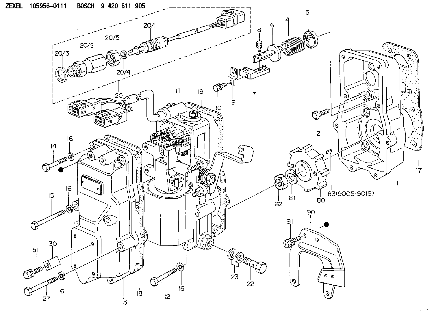
| 1. | [1] | 159560-2600 | GOVERNOR HOUSING |
| 2. | [8] | 139006-4100 | BLEEDER SCREW |
| 4. | [1] | 159564-0000 | COILED SPRING |
| 5. | [1] | 159564-4000 | SLOTTED WASHER |
| 6. | [1] | 159564-4100 | SLOTTED WASHER |
| 7. | [1] | 159564-9021 | CONNECTOR |
| 8. | [1] | 020105-1240 | BLEEDER SCREW M5P0.8L12 |
| 9. | [1] | 159564-0501 | PLATE |
| 9B. | [1] | 159564-6500 | PLATE |
| 9C. | [1] | 159584-5200 | PLATE |
| 10. | [1] | 020105-1240 | BLEEDER SCREW M5P0.8L12 |
| 11. | [1] | 159579-2920 | ACTUATOR |
| 12. | [2] | 020106-4040 | BLEEDER SCREW |
| 13. | [1] | 159561-0700 | GOVERNOR COVER |
| 14. | [4] | 010006-7040 | BLEEDER SCREW M6P1L70 |
| 15. | [2] | 139006-8700 | BLEEDER SCREW |
| 16. | [8] | 014110-6440 | LOCKING WASHER |
| 16. | [8] | 014110-6440 | LOCKING WASHER |
| 16. | [8] | 014110-6440 | LOCKING WASHER |
| 16. | [8] | 014110-6440 | LOCKING WASHER |
| 17. | [1] | 159584-7600 | GASKET |
| 18. | [1] | 154390-0400 | GASKET |
| 19. | [1] | 154390-0500 | GASKET |
| 20. | [1] | 154612-3920 | RACK SENSOR ASSY |
| 20/1. | [1] | 479775-3220 | RACK SENSOR |
| 20/2. | [1] | 154614-8800 | JOINT CONNECTION |
| 20/3. | [1] | 026524-3040 | GASKET |
| 20/4. | [1] | 029310-6280 | SHIM D11.5&6.4T1.50 |
| 20/5. | [1] | 154614-1900 | UNION NUT |
| 22. | [1] | 029731-4680 | EYE BOLT |
| 23. | [2] | 029331-4230 | GASKET |
| 27. | [2] | 139006-1300 | BLEEDER SCREW M6P1L76 |
| 30. | [1] | 159564-4900 | CLAMPING BAND |
| 51. | [1] | 020106-1040 | BLEEDER SCREW M6P1L12 |
| 80. | [1] | 159564-8600 | TOOTHED GEAR |
| 81. | [1] | 014111-2420 | LOCKING WASHER |
| 82. | [1] | 013031-2120 | UNION NUT |
| 83. | [1] | 025803-1310 | WOODRUFF KEY |
| 90. | [1] | 159584-3321 | BRACKET |
| 91. | [2] | 020106-2040 | BLEEDER SCREW M6P1L20 |
| 900S. | [1] | 025803-1310 | WOODRUFF KEY |
| 901S. | [1] | 025803-1610 | WOODRUFF KEY |
Include in #1:
107691-2621
as GOVERNOR
Cross reference number
Zexel num
Bosch num
Firm num
Name
Information:
941B 80H3884-Up
(1) Remove the engine from the machine; see the Service Manual for the procedure. Put both engines, new and old, in a position that will give good access to their front, rear, top and both sides. For those engines that were equipped with glow plugs, either remove the wire from the heat-start switch to the glow plug lead assembly, or put tape over the end of the wire when it is disconnected. This wire will not be needed because the new engine does not have glow plugs.(2) From the old engine, remove the crankshaft pulley and hub, engine front support, the rear supports (from the sides of the flywheel housing) and the flywheel. Install these
(1) Remove the engine from the machine; see the Service Manual for the procedure. Put both engines, new and old, in a position that will give good access to their front, rear, top and both sides. For those engines that were equipped with glow plugs, either remove the wire from the heat-start switch to the glow plug lead assembly, or put tape over the end of the wire when it is disconnected. This wire will not be needed because the new engine does not have glow plugs.(2) From the old engine, remove the crankshaft pulley and hub, engine front support, the rear supports (from the sides of the flywheel housing) and the flywheel. Install these