Information actuator
BOSCH
F 019 Z2E 568
f019z2e568
ZEXEL
105955-0112
1059550112
Rating:
Scheme ###:
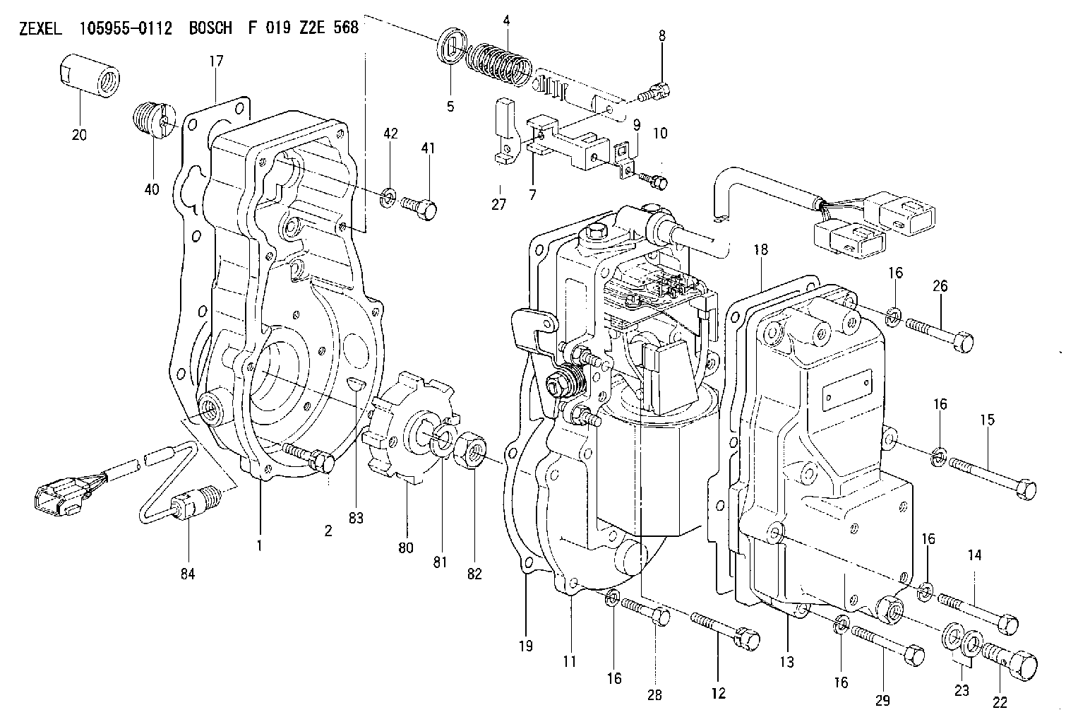
| 1. | [1] | 159570-0200 | GOVERNOR HOUSING |
| 2. | [6] | 020118-2840 | BLEEDER SCREW |
| 4. | [1] | 159574-0100 | COILED SPRING |
| 5. | [1] | 153400-0200 | SLOTTED WASHER |
| 7. | [1] | 159574-0200 | CONNECTOR |
| 8. | [1] | 020106-2040 | BLEEDER SCREW M6P1L20 |
| 9. | [1] | 159564-0504 | PLATE |
| 10. | [1] | 020105-0840 | BLEEDER SCREW M5P0.5L8 |
| 11. | [1] | 159580-0722 | ACTUATOR |
| 11/1. | [1] | 159572-0120 | PLATE;GOV. |
| 11/2. | [1] | 159573-3020 | STRAP |
| 11/3. | [1] | 159563-1700 | LEVER SHAFT |
| 11/4. | [2] | 029311-0170 | SHIM |
| 11/5. | [2] | 016500-0710 | O-RING |
| 11/6. | [2] | 014011-0140 | PLAIN WASHER D22&10.5T1.6 |
| 11/7. | [1] | 016010-0940 | LOCKING WASHER |
| 11/9. | [4] | 020106-2540 | BLEEDER SCREW M6P1L25 |
| 11/11. | [4] | 020105-2040 | BLEEDER SCREW M5P0.8L20 |
| 11/13. | [1] | 159587-6320 | CABLE SET |
| 11/14. | [2] | 159563-2100 | BLEEDER SCREW |
| 11/16. | [1] | 159573-1900 | CONTROL LEVER |
| 11/17. | [1] | 159563-4800 | COILED SPRING |
| 11/18. | [1] | 159563-1800 | BUSHING |
| 11/19. | [1] | 014110-8440 | LOCKING WASHER |
| 11/20. | [1] | 013030-8140 | UNION NUT M8P1.25H5 |
| 11/21. | [1] | 159563-1000 | FLAT-HEAD SCREW |
| 11/22. | [1] | 155615-1700 | FLAT-HEAD SCREW |
| 11/23. | [2] | 029240-6010 | UNION NUT M6P1.0H5* |
| 11/34. | [1] | 159563-8400 | FLAT-HEAD SCREW |
| 11/42. | [2] | 014110-6440 | LOCKING WASHER |
| 12. | [2] | 010006-6040 | BLEEDER SCREW |
| 13. | [1] | 159561-0520 | GOVERNOR COVER |
| 14. | [2] | 010006-4040 | BLEEDER SCREW M6P1L40 |
| 15. | [2] | 010006-6040 | BLEEDER SCREW |
| 16. | [14] | 014110-6440 | LOCKING WASHER |
| 16. | [14] | 014110-6440 | LOCKING WASHER |
| 16. | [14] | 014110-6440 | LOCKING WASHER |
| 16. | [14] | 014110-6440 | LOCKING WASHER |
| 16. | [14] | 014110-6440 | LOCKING WASHER |
| 17. | [1] | 159574-1200 | GASKET |
| 18. | [1] | 154390-0400 | GASKET |
| 19. | [1] | 159574-0900 | GASKET |
| 20. | [1] | 155404-1400 | CAP |
| 22. | [1] | 029731-4680 | EYE BOLT |
| 23. | [2] | 029341-4130 | GASKET D20&13.8T2* |
| 26. | [2] | 159574-0600 | BLEEDER SCREW |
| 27. | [1] | 159574-0500 | PLATE |
| 28. | [4] | 010006-2840 | BLEEDER SCREW M6P1L28 |
| 29. | [2] | 010006-3840 | BLEEDER SCREW |
| 40. | [1] | 154007-0500 | ADAPTOR |
| 41. | [1] | 010038-1840 | BLEEDER SCREW M8P1.25L18 |
| 42. | [1] | 014110-8440 | LOCKING WASHER |
| 80. | [1] | 159574-1100 | TOOTHED GEAR |
| 81. | [1] | 014111-8420 | LOCKING WASHER |
| 82. | [1] | 013131-8120 | UNION NUT |
| 83. | [1] | 025805-1910 | WOODRUFF KEY |
| 84. | [1] | 479748-2020 | PULSE GENERATOR |
Include in #1:
103662-3355
as GOVERNOR
Cross reference number
Zexel num
Bosch num
Firm num
Name
105955-0112
F 019 Z2E 568
ACTUATOR
K 14JT ACTUATOR GOV
K 14JT ACTUATOR GOV
Information:
(4) VOP (Valve Opening Pressure) Test A. Open the gauge protector valve [0-34500 kPa (0-5000 psi) gauge].B. Increase the pressure until test oil flows from the nozzle tip.C. Write down the VOP. (5) Pressure Loss Test A. Increase the pressure to 690 kPa (100 psi) less than the VOP.B. Close the pump isolator valve (6).C. Use the gauge protector valve (3), [0-34500 kPa (0-5000 psi) gauge] to adjust pressure to 690 kPa (100 psi) less than the VOP.D. After 30 seconds, write down the pressure loss. (6) Adjustment of Valve Opening Pressure If spray characteristics are satisfactory, adjust the valve unseating pressure: Use 7B2591 Cap Wrench (7) to remove the cap. Remove lift screw locknut (8) and loosen lift adjustment screw (9) approximately three turns, so it does not interfere with the pressure adjustment. Loosen pressure adjustment locknut (10).E. Install the nozzle on the 5P4150 Nozzle Tester. F. Use 7B2601 Wrench (11) and adjust the VOP. G. Remove the valve from the nozzle tester and put it in a vise. Install lift adjustment screw locknut (8).H. Use the 6B1655 Wrench to turn lift adjusting screw (9) down lightly against the stem of the fuel valve spring.I. Clamp the needle lift adjustment fixture to the fuel valve body.J. Use a thickness gauge and adjust screw (12) until there is a clearance of 0.43 (.017") between screw (12) and lift adjustment screw (9).K. Hold screw (12) in position with clamping screw (13).L. Remove the thickness gauge and loosen lift adjustment screw (9) until there is 0.3 (.010") clearance between screw (9) and screw (12), after lift screw locknut (8) is tightened with the 7B2587 Wrench. The correct needle lift setting for all valves is 0.177 (.007").Cleaning Needle, Nozzle And Nozzle End Of Flat Seat Valves (Except 1P1795 Master Valves)
(1) Remove cap (1), bonnet (2) or unseating pressure adjusting screw, spring retainer, spring (3) and spring stem (4). Put the correct needle extracting tool (5) through the valve body and tighten over the end of the needle. If the needle is tight, install a new valve service group, or disassemble and clean the valve according to the procedure that follows. (2) If a fuel valve has a chip of scale, metal or foreign material on the seat, this will prevent the needle, from seating on the spray valve nozzle end, and cause the inner surface of the nozzle end and the needle end to become coated with carbon. Put carbon scraper (6) in the needle extracting tool and insert it into the nozzle bore and against the nozzle end; carefully turn the tool one revolution, with a slight pressure to remove the carbon. The cutting surface of scraper (6) has been lapped as perfectly flat and square with the center line of the tool as possible. Unless it remains so, it cannot effectively remove carbon. Handle this tool with care. Two scrapers are provided, so if one becomes marred, the second can be used while another is being obtained.
(1) Remove cap (1), bonnet (2) or unseating pressure adjusting screw, spring retainer, spring (3) and spring stem (4). Put the correct needle extracting tool (5) through the valve body and tighten over the end of the needle. If the needle is tight, install a new valve service group, or disassemble and clean the valve according to the procedure that follows. (2) If a fuel valve has a chip of scale, metal or foreign material on the seat, this will prevent the needle, from seating on the spray valve nozzle end, and cause the inner surface of the nozzle end and the needle end to become coated with carbon. Put carbon scraper (6) in the needle extracting tool and insert it into the nozzle bore and against the nozzle end; carefully turn the tool one revolution, with a slight pressure to remove the carbon. The cutting surface of scraper (6) has been lapped as perfectly flat and square with the center line of the tool as possible. Unless it remains so, it cannot effectively remove carbon. Handle this tool with care. Two scrapers are provided, so if one becomes marred, the second can be used while another is being obtained.
Have questions with 105955-0112?
Group cross 105955-0112 ZEXEL
105955-0112
F 019 Z2E 568
ACTUATOR