Information actuator
BOSCH
9 420 613 793
9420613793
ZEXEL
105953-0010
1059530010
HINO
223202370A
223202370a
Rating:
Scheme ###:
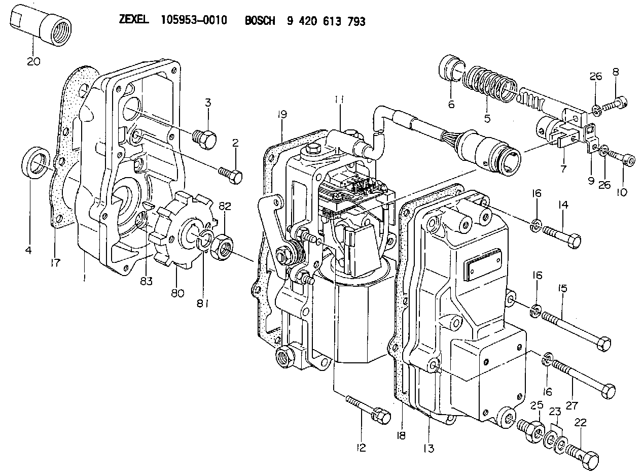
| 1. | [1] | 159560-0700 | GOVERNOR HOUSING |
| 2. | [6] | 029010-6810 | BLEEDER SCREW |
| 3. | [1] | 020018-1840 | BLEEDER SCREW M8P1.25L18 |
| 4. | [1] | 029621-7050 | PACKING RING |
| 5. | [1] | 159564-1200 | COILED SPRING |
| 6. | [1] | 159564-3600 | SLOTTED WASHER |
| 7. | [1] | 159564-1600 | CONNECTOR |
| 8. | [1] | 159584-9100 | HEX-SOCKET-HEAD CAP SCREW |
| 9. | [1] | 159564-0504 | PLATE |
| 10. | [1] | 159584-9000 | HEX-SOCKET-HEAD CAP SCREW |
| 11. | [1] | 159567-1321 | ACTUATOR |
| 11/1. | [1] | 159562-1220 | PLATE;GOV. |
| 11/2. | [1] | 159583-1020 | STRAP |
| 11/3. | [1] | 159563-1700 | LEVER SHAFT |
| 11/4. | [2] | 029311-0170 | SHIM |
| 11/5. | [2] | 016500-0710 | O-RING |
| 11/6. | [2] | 014011-0140 | PLAIN WASHER D22&10.5T1.6 |
| 11/8. | [1] | 016010-0940 | LOCKING WASHER |
| 11/10. | [4] | 020106-2540 | BLEEDER SCREW M6P1L25 |
| 11/12. | [4] | 020105-2040 | BLEEDER SCREW M5P0.8L20 |
| 11/17. | [1] | 159568-0620 | CABLE SET |
| 11/18. | [2] | 020106-1440 | BLEEDER SCREW M6P1.0L14 |
| 11/21. | [1] | 159563-3720 | CONTROL LEVER |
| 11/22. | [1] | 159563-1600 | COILED SPRING |
| 11/23. | [1] | 159563-1800 | BUSHING |
| 11/24. | [1] | 014110-8440 | LOCKING WASHER |
| 11/25. | [1] | 013030-8140 | UNION NUT M8P1.25H5 |
| 11/26. | [1] | 159563-1000 | FLAT-HEAD SCREW |
| 11/27. | [2] | 155615-1700 | FLAT-HEAD SCREW |
| 11/28. | [2] | 029240-6010 | UNION NUT M6P1.0H5* |
| 11/29. | [1] | 159563-2701 | BRACKET |
| 11/30. | [1] | 479749-2400 | PULSE GENERATOR |
| 11/31. | [1] | 159592-0300 | UNION NUT |
| 11/32. | [2] | 020106-1440 | BLEEDER SCREW M6P1.0L14 |
| 12. | [2] | 020106-4040 | BLEEDER SCREW |
| 13. | [1] | 159561-0820 | GOVERNOR COVER |
| 14. | [4] | 010006-7040 | BLEEDER SCREW M6P1L70 |
| 15. | [2] | 010006-5540 | BLEEDER SCREW M6P1L55 4T |
| 16. | [8] | 014110-6440 | LOCKING WASHER |
| 16. | [8] | 014110-6440 | LOCKING WASHER |
| 16. | [8] | 014110-6440 | LOCKING WASHER |
| 17. | [1] | 154390-0000 | GASKET |
| 18. | [1] | 154390-0400 | GASKET |
| 19. | [1] | 154390-0500 | GASKET |
| 20. | [1] | 155404-0200 | CAP |
| 22. | [1] | 029731-4680 | EYE BOLT |
| 23. | [2] | 139514-0300 | GASKET |
| 25. | [1] | 154007-0200 | ADAPTOR |
| 26. | [2] | 014110-5440 | LOCKING WASHER |
| 26. | [2] | 014110-5440 | LOCKING WASHER |
| 27. | [2] | 139006-1300 | BLEEDER SCREW M6P1L76 |
| 80. | [1] | 159564-1900 | TOOTHED GEAR |
| 81. | [1] | 014111-2420 | LOCKING WASHER |
| 82. | [1] | 013031-2120 | UNION NUT |
| 83. | [1] | 025803-1610 | WOODRUFF KEY |
Include in #1:
101602-2301
as GOVERNOR
Cross reference number
Zexel num
Bosch num
Firm num
Name
105953-0010
9 420 613 793
223202370A HINO
ACTUATOR
K 14JT ACTUATOR GOV
K 14JT ACTUATOR GOV
Information:
Typical Example1. Remove bolts (1) from the alternator bracket.2. Remove the bolts that hold plate (3) and remove the plate.3. Disconnect water line (2) from the air compressor. Turn the water line tee toward the lifting bracket in order to provide clearance to remove the head bolt. 4. Remove bolts (4) and (5) that hold the cylinder head assembly to the cylinder block.5. Fasten a hoist and remove the cylinder head assembly. The weight is approximately 135 kg (300 lb).
Do not put the cylinder head assembly down on a flat surface. This can cause damage to the fuel injection valves.
6. Remove the gasket and seals from the spacer plate.Install Cylinder Head Assembly
Be sure a new gasket has been installed between the spacer plate and the cylinder block. See topic, "Remove & Install Spacer Plate". 1. Thoroughly clean the spacer plate and the bottom surface of the cylinder head assembly. Install a new head gasket, new seals (1) and two O-ring seals (2). 2. Fasten a hoist and put the cylinder head assembly (3) in position on the cylinder block.3. Tighten the bolts in sequence shown in Illustration D11970.
(1) Large bolts (3/4 inch). Put 6V4876 Molycoat Paste Lubricant on bolt threads and between washers and underside of bolt heads.(2) Small bolts (3/8 inch). See Step 4h.4. Install the cylinder head bolts and washers. Tighten the bolts in sequence shown.a. Tighten bolts 1 through 14 in number sequence to 270 25 N m (200 20 lb ft).b. Tighten bolts 1 through 14 in number sequence to 470 20 N m (345 15 lb ft).c. Tighten bolts 1 through 14 in number sequence again to 470 20 N m (345 15 lb ft).d. Install the rocker arm shafts for the engine valves and the remaining (3/4 in) bolts and/or compression brake studs.e. Tighten bolts 15 through 26 in number sequence to 270 25 N m (200 20 lb ft).f. Tighten bolts 15 through 26 in number sequence to 450 20 N m (330 15 lb ft).g. Tighten bolts 15 through 26 in number sequence again to 450 20 N m (330 15 lb ft).h. Tighten the thirteen small bolts (2) to 45 7 N m (33 5 lb ft).5. Make an adjustment to the valves to have a clearance of 0.38 mm (.015 in) for intake and 0.76 mm (.030 in) for exhaust. Tighten the locknuts for the valve adjustment screws to a torque of 28 4 N m (21 3 lb ft).6. Install the valve cover bases and the inner fuel lines. See topic, "Install Rocker Shaft Assemblies & Push Rods".7. Install the valve covers. See topic, "Install Valve Covers".
Typical Example8. Install plate (4).9. Connect the water line to the air compressor.10. Install bolts (5) for the alternator bracket.End By:a. install exhaust manifoldb. install fuel injection linesc. install aftercooler housingd. install water temperature regulatore. install rocker shaft assemblies and push rods
Have questions with 105953-0010?
Group cross 105953-0010 ZEXEL
Hino
Hino
105953-0010
9 420 613 793
223202370A
ACTUATOR