Information actuator
BOSCH
F 019 Z4E 016
f019z4e016
ZEXEL
105952-2930
1059522930
Rating:
Scheme ###:
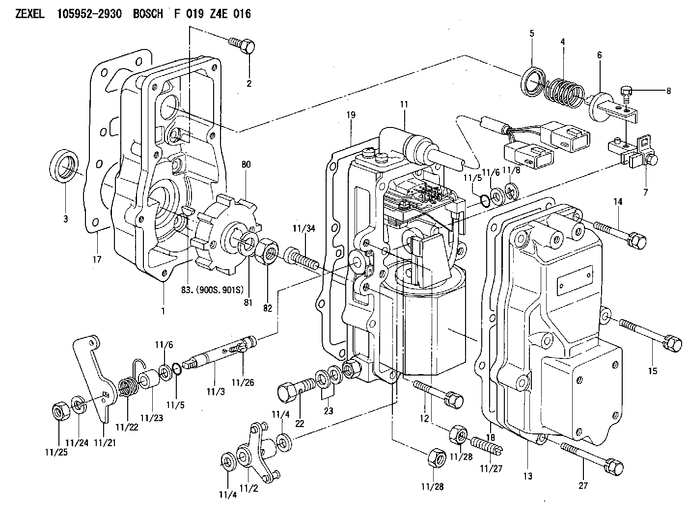
| 1. | [1] | 159560-0100 | GOVERNOR HOUSING |
| 2. | [8] | 139006-4100 | BLEEDER SCREW |
| 3. | [1] | 029621-7050 | PACKING RING |
| 4. | [1] | 159564-5200 | COILED SPRING |
| 5. | [1] | 159564-4000 | SLOTTED WASHER |
| 6. | [1] | 159635-8800 | SLOTTED WASHER |
| 7. | [1] | 159636-4521 | CONNECTOR |
| 7B. | [1] | 159636-4621 | CONNECTOR |
| 7C. | [1] | 159636-4721 | CONNECTOR |
| 8. | [1] | 020105-1240 | BLEEDER SCREW M5P0.8L12 |
| 11. | [1] | 159579-7220 | ACTUATOR |
| 11/2. | [1] | 159636-5020 | STRAP |
| 11/3. | [1] | 159563-1700 | LEVER SHAFT |
| 11/4. | [2] | 029311-0170 | SHIM |
| 11/4. | [2] | 029311-0170 | SHIM |
| 11/5. | [2] | 159635-0200 | O-RING |
| 11/5. | [2] | 159635-0200 | O-RING |
| 11/6. | [2] | 014011-0140 | PLAIN WASHER D22&10.5T1.6 |
| 11/6. | [2] | 014011-0140 | PLAIN WASHER D22&10.5T1.6 |
| 11/8. | [1] | 016010-0940 | LOCKING WASHER |
| 11/10. | [4] | 139006-9100 | BLEEDER SCREW |
| 11/12. | [4] | 020105-2040 | BLEEDER SCREW M5P0.8L20 |
| 11/17/6. | [1] | 016520-2410 | O-RING |
| 11/17/8. | [1] | 159910-3300 | SOCKET HOUSING |
| 11/17/12. | [1] | 159910-3500 | SOCKET HOUSING |
| 11/17/19. | [1] | 159910-3400 | HOLDER |
| 11/17/20. | [1] | 159910-3600 | HOLDER |
| 11/18. | [4] | 020106-1840 | BLEEDER SCREW M6P1L18 |
| 11/19. | [1] | 131002-2700 | ADAPTOR |
| 11/21. | [1] | 159583-2800 | CONTROL LEVER |
| 11/22. | [1] | 159563-4800 | COILED SPRING |
| 11/23. | [1] | 159563-1800 | BUSHING |
| 11/24. | [1] | 014110-8440 | LOCKING WASHER |
| 11/25. | [1] | 013030-8140 | UNION NUT M8P1.25H5 |
| 11/26. | [1] | 159563-1000 | FLAT-HEAD SCREW |
| 11/27. | [1] | 155615-1700 | FLAT-HEAD SCREW |
| 11/28. | [2] | 029240-6010 | UNION NUT M6P1.0H5* |
| 11/28. | [2] | 029240-6010 | UNION NUT M6P1.0H5* |
| 11/32. | [2] | 020106-1440 | BLEEDER SCREW M6P1.0L14 |
| 11/34. | [1] | 159563-8400 | FLAT-HEAD SCREW |
| 12. | [2] | 020106-4040 | BLEEDER SCREW |
| 13. | [1] | 159561-0400 | GOVERNOR COVER |
| 14. | [4] | 139006-9300 | BLEEDER SCREW |
| 15. | [2] | 139006-9200 | BLEEDER SCREW |
| 17. | [1] | 154371-5600 | GASKET |
| 18. | [1] | 154390-0400 | GASKET |
| 19. | [1] | 154390-0500 | GASKET |
| 22. | [1] | 029731-4680 | EYE BOLT |
| 23. | [2] | 029341-4130 | GASKET D20&13.8T2* |
| 27. | [2] | 139006-9400 | BLEEDER SCREW |
| 60. | [2] | 013020-6040 | UNION NUT M6P1H5 |
| 80. | [1] | 159584-0100 | TOOTHED GEAR |
| 81. | [1] | 014111-2420 | LOCKING WASHER |
| 82. | [1] | 013031-2120 | UNION NUT |
| 83. | [1] | 025803-1310 | WOODRUFF KEY |
| 900S. | [1] | 025803-1310 | WOODRUFF KEY |
| 901S. | [1] | 025803-1610 | WOODRUFF KEY |
Cross reference number
Zexel num
Bosch num
Firm num
Name
105952-2930
F 019 Z4E 016
ACTUATOR
K 14JT ACTUATOR GOV
K 14JT ACTUATOR GOV
Information:
Start By:a. disassemble governorb. remove fuel injection pumps 1. Remove the six lifters from the fuel pump housing.2. Remove rack (1) and camshaft (2) from the fuel pump housing. If necessary, use a soft hammer to push the camshaft out the governor end. 3. Use Tool (A) and remove the three camshaft bearings from the fuel pump housing. 4. Remove rack bearing (4) and the other rack bearing from the fuel pump housing.5. Remove dowel (3) from the fuel pump housing. 6. Remove bolts (6), cover (5) and the gasket from the fuel pump housing.Assemble Fuel Injection Pump Housing
1. Install gasket (7) and cover (5) on the side of the fuel pump housing. 2. Use Tool (B) and install the D shaped rack bearing into the governor and fuel pump drive side of the fuel pump housing 87.0 0.5 mm (3.42 .02 in) from outside surface (X).3. The inside flat diameter after assembly must be 11.178 0.050 mm (.440 .002 in) and the inside large diameter must be 12.767 0.058 mm (.503 .002 in). 4. Install dowel (3) in the fuel pump housing 6.0 0.5 (.24 .02 in) above the outside surface.5. Use Tool (C) and install the rack bearing into the fuel pump housing 7.16 0.13 mm (.282 .005 in) below the surface of the pump housing.6. The inside diameter of the bearing after assembly must be 12.746 0.045 (.502 .002 in). 7. Use Tool (A) and install the three camshaft bearings in the fuel pump housing with the oil holes in the bearings 30 3 degrees from the horizontal center line toward the plugged holes in the fuel pump housing.8. The inside diameter of all three bearings after assembly must be 68.399 0.038 mm (2.6905 .0015 in). 9. Make sure bearing (8) on the governor and fuel pump drive is installed 1.0 0.5 mm (.04 .02 in) below surface (Y).10. Make sure middle bearing (9) is 218 0.3 mm (8.6 .01 in) below surface (Y). 11. Make sure bearing (10) governor side is 1.00 0.25 mm (.040 .010 in) below the outside surface.12. Remove the plugs from the side of the fuel pump housing. The oil holes in the bearings must in alignment with holes (11) in the fuel pump housing. If the bearings are not in alignment, remove them and install again. 13. Make an alignment of rack (1) and install it in the fuel pump housing.14. Install the six lifters in the fuel pump housing. Make sure the pins in the lifter are on the same side as the dowels in the fuel pump housing.End By:a. install fuel injection pumpsb. assemble governor
1. Install gasket (7) and cover (5) on the side of the fuel pump housing. 2. Use Tool (B) and install the D shaped rack bearing into the governor and fuel pump drive side of the fuel pump housing 87.0 0.5 mm (3.42 .02 in) from outside surface (X).3. The inside flat diameter after assembly must be 11.178 0.050 mm (.440 .002 in) and the inside large diameter must be 12.767 0.058 mm (.503 .002 in). 4. Install dowel (3) in the fuel pump housing 6.0 0.5 (.24 .02 in) above the outside surface.5. Use Tool (C) and install the rack bearing into the fuel pump housing 7.16 0.13 mm (.282 .005 in) below the surface of the pump housing.6. The inside diameter of the bearing after assembly must be 12.746 0.045 (.502 .002 in). 7. Use Tool (A) and install the three camshaft bearings in the fuel pump housing with the oil holes in the bearings 30 3 degrees from the horizontal center line toward the plugged holes in the fuel pump housing.8. The inside diameter of all three bearings after assembly must be 68.399 0.038 mm (2.6905 .0015 in). 9. Make sure bearing (8) on the governor and fuel pump drive is installed 1.0 0.5 mm (.04 .02 in) below surface (Y).10. Make sure middle bearing (9) is 218 0.3 mm (8.6 .01 in) below surface (Y). 11. Make sure bearing (10) governor side is 1.00 0.25 mm (.040 .010 in) below the outside surface.12. Remove the plugs from the side of the fuel pump housing. The oil holes in the bearings must in alignment with holes (11) in the fuel pump housing. If the bearings are not in alignment, remove them and install again. 13. Make an alignment of rack (1) and install it in the fuel pump housing.14. Install the six lifters in the fuel pump housing. Make sure the pins in the lifter are on the same side as the dowels in the fuel pump housing.End By:a. install fuel injection pumpsb. assemble governor
Have questions with 105952-2930?
Group cross 105952-2930 ZEXEL
105952-2930
F 019 Z4E 016
ACTUATOR