Information actuator
BOSCH
F 019 Z3E 568
f019z3e568
ZEXEL
105952-2782
1059522782
Rating:
Scheme ###:
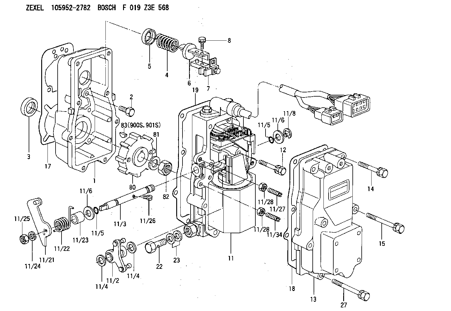
| 1. | [1] | 159560-0100 | GOVERNOR HOUSING |
| 2. | [8] | 139006-4100 | BLEEDER SCREW |
| 3. | [1] | 029621-7050 | PACKING RING |
| 4. | [1] | 159564-5200 | COILED SPRING |
| 5. | [1] | 159564-4000 | SLOTTED WASHER |
| 6. | [1] | 159564-4100 | SLOTTED WASHER |
| 7. | [1] | 159636-4520 | CONNECTOR |
| 7B. | [1] | 159636-4620 | CONNECTOR |
| 7C. | [1] | 159636-4720 | CONNECTOR |
| 8. | [1] | 020105-1240 | BLEEDER SCREW M5P0.8L12 |
| 11. | [1] | 159579-5421 | ACTUATOR |
| 11/1. | [1] | 159562-0720 | PLATE;GOV. |
| 11/2. | [1] | 159636-5020 | STRAP |
| 11/3. | [1] | 159563-1700 | LEVER SHAFT |
| 11/4. | [2] | 029311-0170 | SHIM |
| 11/4. | [2] | 029311-0170 | SHIM |
| 11/5. | [2] | 016500-0710 | O-RING |
| 11/5. | [2] | 016500-0710 | O-RING |
| 11/6. | [2] | 014011-0140 | PLAIN WASHER D22&10.5T1.6 |
| 11/6. | [2] | 014011-0140 | PLAIN WASHER D22&10.5T1.6 |
| 11/8. | [1] | 016010-0940 | LOCKING WASHER |
| 11/9. | [1] | 159585-0020 | LINEAR DC MOTOR |
| 11/10. | [4] | 020106-2540 | BLEEDER SCREW M6P1L25 |
| 11/11. | [1] | 159566-0720 | RACK SENSOR |
| 11/12. | [4] | 020105-2040 | BLEEDER SCREW M5P0.8L20 |
| 11/16. | [1] | 159565-2400 | LIP |
| 11/17. | [1] | 159568-8820 | CABLE SET |
| 11/18. | [2] | 020106-1440 | BLEEDER SCREW M6P1.0L14 |
| 11/19. | [1] | 131002-2700 | ADAPTOR |
| 11/21. | [1] | 159583-2800 | CONTROL LEVER |
| 11/22. | [1] | 159563-4800 | COILED SPRING |
| 11/23. | [1] | 159563-1800 | BUSHING |
| 11/24. | [1] | 014110-8440 | LOCKING WASHER |
| 11/25. | [1] | 013030-8140 | UNION NUT M8P1.25H5 |
| 11/26. | [1] | 159563-1000 | FLAT-HEAD SCREW |
| 11/27. | [1] | 155615-1700 | FLAT-HEAD SCREW |
| 11/28. | [2] | 029240-6010 | UNION NUT M6P1.0H5* |
| 11/28. | [2] | 029240-6010 | UNION NUT M6P1.0H5* |
| 11/29. | [1] | 159563-2701 | BRACKET |
| 11/30. | [1] | 479749-2400 | PULSE GENERATOR |
| 11/31. | [1] | 159592-0300 | UNION NUT |
| 11/32. | [2] | 020106-1440 | BLEEDER SCREW M6P1.0L14 |
| 11/34. | [1] | 159563-8400 | FLAT-HEAD SCREW |
| 12. | [2] | 020106-4040 | BLEEDER SCREW |
| 13. | [1] | 159561-0400 | GOVERNOR COVER |
| 14. | [4] | 139006-9300 | BLEEDER SCREW |
| 15. | [2] | 139006-9200 | BLEEDER SCREW |
| 17. | [1] | 154371-5600 | GASKET |
| 18. | [1] | 154390-0400 | GASKET |
| 19. | [1] | 154390-0500 | GASKET |
| 22. | [1] | 029731-4680 | EYE BOLT |
| 23. | [2] | 029341-4130 | GASKET D20&13.8T2* |
| 27. | [2] | 139006-9400 | BLEEDER SCREW |
| 80. | [1] | 159564-9200 | TOOTHED GEAR |
| 81. | [1] | 014111-2420 | LOCKING WASHER |
| 82. | [1] | 013031-2120 | UNION NUT |
| 83. | [1] | 025803-1310 | WOODRUFF KEY |
| 900S. | [1] | 025803-1310 | WOODRUFF KEY |
| 901S. | [1] | 025803-1610 | WOODRUFF KEY |
Include in #1:
106685-4373
as GOVERNOR
Cross reference number
Zexel num
Bosch num
Firm num
Name
Information:
Start By:a. remove valve cover 1. Disconnect fuel line nut (1). Remove nut (2) and O-ring seal. Disconnect fuel line nut (4) and remove fuel line assembly (3).
Put protection caps on all fuel line openings.
2. Remove retainer (5) from fuel adapter with Tool (B). 3. Install Tooling (C) and remove fuel nozzle assembly from adapter. 4. Install Tool (D) and remove adapter (6). 5. Remove carbon seal stop (7) with Tool (E). 6. Remove washer (8) and bleed screw (9) from fuel nozzle assembly (10). The following steps are for the installation of the fuel injection nozzles and adapters. 7. Install new carbon seal stop (7) with Tool (E). 8. Make sure the correct washer (8) is used when the nozzle assembly (10) is installed. Always use a new washer anytime the bleed screw (9) is loosened or removed. Install fuel nozzle assembly (10) in adapter (6). Install retainer (5) to a torque of 48 7 N m (35 5 lb ft). 9. Put 5P-3931 Anti-Seize Compound on the threads of the adapter before installation. Install fuel adapter (6) with Tool (D). Torque for the adapter is 200 14 N m (150 10 lb ft).10. Install fuel injection line assembly (3) (finger tighten connections first). Install the O-ring seal and nut (2) to a torque of 30 7 N m (22 5 lb ft). Reconnect fuel line nut (1) to a torque of 40 7 N m (30 5 lb ft). Use Tool (A) to reconnect fuel line nut (4) to a torque of 40 7 N m (30 5 lb ft).End By:a. install valve cover