Information actuator
BOSCH
F 019 Z3E 244
f019z3e244
ZEXEL
105952-2781
1059522781

Rating:
Scheme ###:
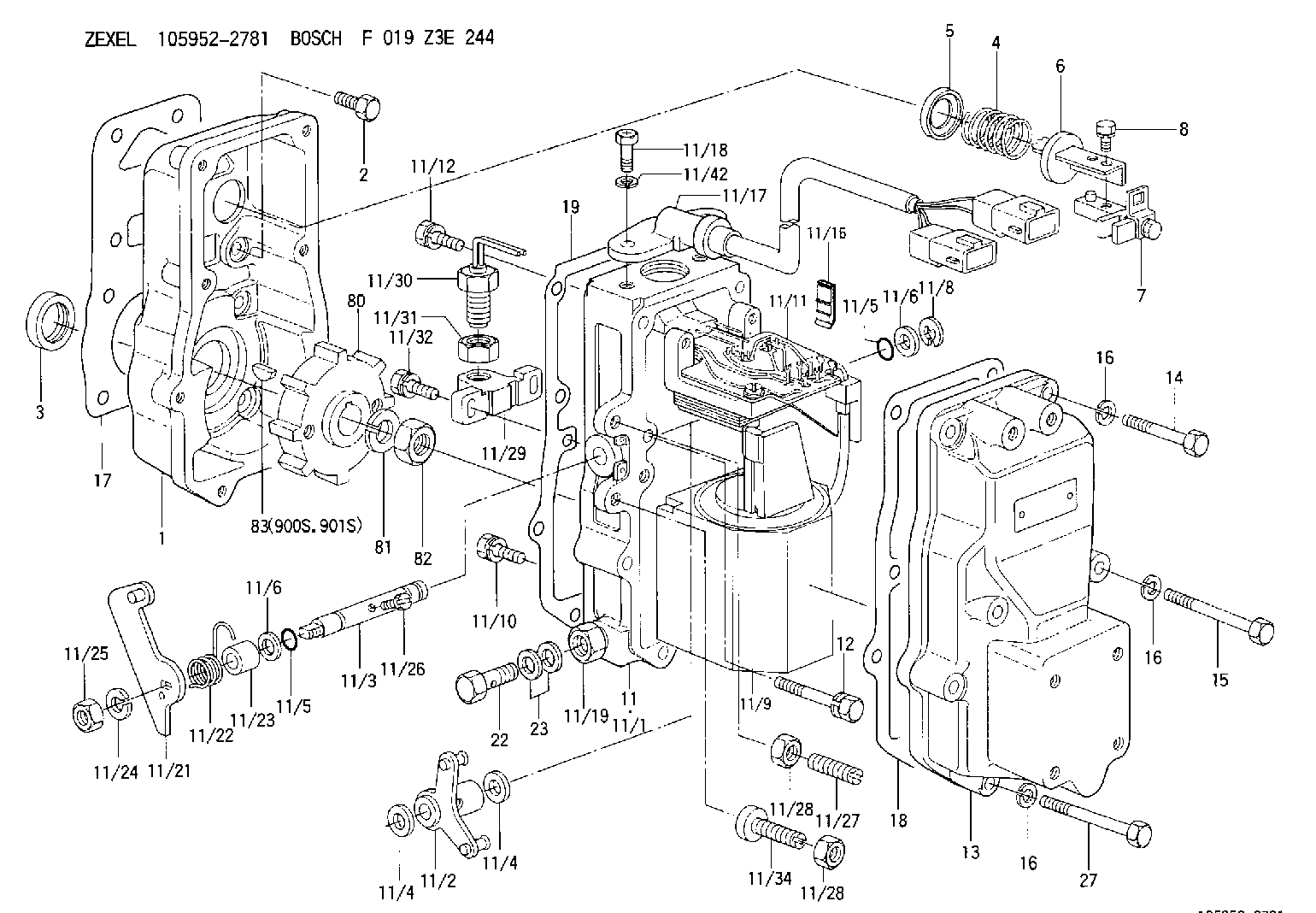
| 1. | [1] | 159560-0100 | GOVERNOR HOUSING |
| 2. | [8] | 139006-4100 | BLEEDER SCREW |
| 3. | [1] | 029621-7050 | PACKING RING |
| 4. | [1] | 159564-0000 | COILED SPRING |
| 5. | [1] | 159564-4000 | SLOTTED WASHER |
| 6. | [1] | 159564-4100 | SLOTTED WASHER |
| 7. | [1] | 159636-4520 | CONNECTOR |
| 7B. | [1] | 159636-4620 | CONNECTOR |
| 7C. | [1] | 159636-4720 | CONNECTOR |
| 8. | [1] | 020105-1240 | BLEEDER SCREW M5P0.8L12 |
| 11. | [1] | 159579-5421 | ACTUATOR |
| 11/1. | [1] | 159562-0720 | PLATE;GOV. |
| 11/2. | [1] | 159636-5020 | STRAP |
| 11/3. | [1] | 159563-1700 | LEVER SHAFT |
| 11/4. | [2] | 029311-0170 | SHIM |
| 11/4. | [2] | 029311-0170 | SHIM |
| 11/5. | [2] | 016500-0710 | O-RING |
| 11/5. | [2] | 016500-0710 | O-RING |
| 11/6. | [2] | 014011-0140 | PLAIN WASHER D22&10.5T1.6 |
| 11/6. | [2] | 014011-0140 | PLAIN WASHER D22&10.5T1.6 |
| 11/8. | [1] | 016010-0940 | LOCKING WASHER |
| 11/9. | [1] | 159585-0020 | LINEAR DC MOTOR |
| 11/10. | [4] | 020106-2540 | BLEEDER SCREW M6P1L25 |
| 11/11. | [1] | 159566-0720 | RACK SENSOR |
| 11/11/7. | [3] | 012154-0840 | FLAT-HEAD SCREW M4P0.7L8 |
| 11/11/8. | [3] | 014020-4140 | PLAIN WASHER D8&4.5T0.5 |
| 11/11/10. | [2] | 012154-0840 | FLAT-HEAD SCREW M4P0.7L8 |
| 11/11/11. | [2] | 014020-4140 | PLAIN WASHER D8&4.5T0.5 |
| 11/12. | [4] | 020105-2040 | BLEEDER SCREW M5P0.8L20 |
| 11/16. | [1] | 159565-2400 | LIP |
| 11/17. | [1] | 159568-8820 | CABLE SET |
| 11/18. | [2] | 159563-2100 | BLEEDER SCREW |
| 11/19. | [1] | 131002-2700 | ADAPTOR |
| 11/21. | [1] | 159583-2800 | CONTROL LEVER |
| 11/22. | [1] | 159563-4800 | COILED SPRING |
| 11/23. | [1] | 159563-1800 | BUSHING |
| 11/24. | [1] | 014110-8440 | LOCKING WASHER |
| 11/25. | [1] | 013030-8140 | UNION NUT M8P1.25H5 |
| 11/26. | [1] | 159563-1000 | FLAT-HEAD SCREW |
| 11/27. | [1] | 155615-1700 | FLAT-HEAD SCREW |
| 11/28. | [2] | 029240-6010 | UNION NUT M6P1.0H5* |
| 11/28. | [2] | 029240-6010 | UNION NUT M6P1.0H5* |
| 11/29. | [1] | 159563-2701 | BRACKET |
| 11/30. | [1] | 479749-2400 | PULSE GENERATOR |
| 11/31. | [1] | 159592-0300 | UNION NUT |
| 11/32. | [2] | 020106-1440 | BLEEDER SCREW M6P1.0L14 |
| 11/34. | [1] | 159563-8400 | FLAT-HEAD SCREW |
| 11/42. | [2] | 014110-6440 | LOCKING WASHER |
| 12. | [2] | 020106-4040 | BLEEDER SCREW |
| 13. | [1] | 159561-0400 | GOVERNOR COVER |
| 14. | [4] | 010006-7040 | BLEEDER SCREW M6P1L70 |
| 15. | [2] | 010006-5540 | BLEEDER SCREW M6P1L55 4T |
| 16. | [8] | 014110-6440 | LOCKING WASHER |
| 16. | [8] | 014110-6440 | LOCKING WASHER |
| 16. | [8] | 014110-6440 | LOCKING WASHER |
| 17. | [1] | 154371-5600 | GASKET |
| 18. | [1] | 154390-0400 | GASKET |
| 19. | [1] | 154390-0500 | GASKET |
| 22. | [1] | 029731-4680 | EYE BOLT |
| 23. | [2] | 029341-4130 | GASKET D20&13.8T2* |
| 27. | [2] | 139006-1300 | BLEEDER SCREW M6P1L76 |
| 80. | [1] | 159564-9200 | TOOTHED GEAR |
| 81. | [1] | 014111-2420 | LOCKING WASHER |
| 82. | [1] | 013031-2120 | UNION NUT |
| 83. | [1] | 025803-1310 | WOODRUFF KEY |
| 900S. | [1] | 025803-1310 | WOODRUFF KEY |
| 901S. | [1] | 025803-1610 | WOODRUFF KEY |
Include in #1:
106685-4372
as GOVERNOR
Cross reference number
Zexel num
Bosch num
Firm num
Name
Information:
Start By:a. remove valve cover 1. Remove the cover from the flywheel housing and install Tool (A). Turn the crankshaft with Tool (A) until there is no pressure on rocker arm (2).2. Use Tool (B) as shown to move the rocker arm away from push rod (1). Remove push rod (1). 3. Install Tool (C) on the valve lifter. Remove valve lifter (3) from the block. 4. Remove spring guide (4) from the valve lifter.5. Do Steps 1 through 4 again for the other valve lifters and push rods if necessary.Install Valve Lifters & Push Rods
Any time the valve lifter is removed from the machine, a new spring guide must be installed on the valve lifter.1. Install spring guide (1) on valve lifter (2). 2. Put the valve lifter in position on Tool (A) as shown. Make sure spring guide (1) is in position in the groove (slot) in the valve lifter as shown. 3. Use a soft hammer to install Tool (B) over spring guide (1). Make sure the groove in Tool (B) is in alignment with spring guide (1). 4. Put clean engine oil on valve lifter (2). Use Tool (B) to install the valve lifter in the engine block. Make sure the end of the spring guide is in alignment with the small hole in the block.5. When the valve lifter is in position in the block, use Tool (C) to push the valve lifter off of Tool (C). 6. Use Tool (E) to turn the crankshaft to make sure there is not pressure on the push rods and rocker arms.7. Put push rod (3) in position in the block. Use Tool (D) to move rocker arm (4) away from the push rod far enough to put push rod (3) in position under the rocker arm.End By:a. install valve cover
Any time the valve lifter is removed from the machine, a new spring guide must be installed on the valve lifter.1. Install spring guide (1) on valve lifter (2). 2. Put the valve lifter in position on Tool (A) as shown. Make sure spring guide (1) is in position in the groove (slot) in the valve lifter as shown. 3. Use a soft hammer to install Tool (B) over spring guide (1). Make sure the groove in Tool (B) is in alignment with spring guide (1). 4. Put clean engine oil on valve lifter (2). Use Tool (B) to install the valve lifter in the engine block. Make sure the end of the spring guide is in alignment with the small hole in the block.5. When the valve lifter is in position in the block, use Tool (C) to push the valve lifter off of Tool (C). 6. Use Tool (E) to turn the crankshaft to make sure there is not pressure on the push rods and rocker arms.7. Put push rod (3) in position in the block. Use Tool (D) to move rocker arm (4) away from the push rod far enough to put push rod (3) in position under the rocker arm.End By:a. install valve cover