Information actuator
BOSCH
F 019 Z4E 076
f019z4e076
ZEXEL
105952-2772
1059522772
Rating:
Scheme ###:
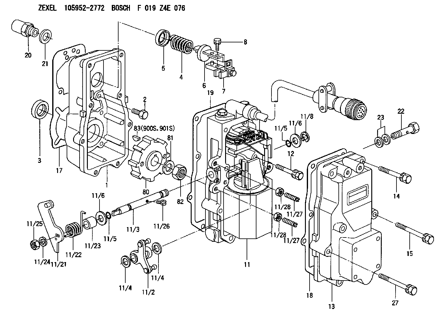
| 1. | [1] | 159560-0100 | GOVERNOR HOUSING |
| 2. | [8] | 139006-4100 | BLEEDER SCREW |
| 3. | [1] | 029621-7050 | PACKING RING |
| 4. | [1] | 159564-5200 | COILED SPRING |
| 5. | [1] | 159564-4000 | SLOTTED WASHER |
| 6. | [1] | 159635-8800 | SLOTTED WASHER |
| 7. | [1] | 159636-4521 | CONNECTOR |
| 7B. | [1] | 159636-4621 | CONNECTOR |
| 7C. | [1] | 159636-4721 | CONNECTOR |
| 8. | [1] | 020105-1240 | BLEEDER SCREW M5P0.8L12 |
| 11. | [1] | 159579-6221 | ACTUATOR |
| 11/2. | [1] | 159636-5020 | STRAP |
| 11/3. | [1] | 159563-1700 | LEVER SHAFT |
| 11/4. | [2] | 029311-0170 | SHIM |
| 11/4. | [2] | 029311-0170 | SHIM |
| 11/5. | [2] | 016500-0710 | O-RING |
| 11/5. | [2] | 016500-0710 | O-RING |
| 11/6. | [2] | 014011-0140 | PLAIN WASHER D22&10.5T1.6 |
| 11/6. | [2] | 014011-0140 | PLAIN WASHER D22&10.5T1.6 |
| 11/8. | [1] | 016010-0940 | LOCKING WASHER |
| 11/10. | [4] | 010206-2520 | HEX-SOCKET-HEAD CAP SCREW |
| 11/12. | [4] | 020105-2040 | BLEEDER SCREW M5P0.8L20 |
| 11/17. | [1] | 159568-5623 | CABLE SET |
| 11/18. | [2] | 020106-1440 | BLEEDER SCREW M6P1.0L14 |
| 11/19. | [1] | 131002-2700 | ADAPTOR |
| 11/21. | [1] | 159563-2300 | CONTROL LEVER |
| 11/22. | [1] | 159563-1600 | COILED SPRING |
| 11/23. | [1] | 159563-1800 | BUSHING |
| 11/24. | [1] | 014110-8440 | LOCKING WASHER |
| 11/25. | [1] | 013030-8140 | UNION NUT M8P1.25H5 |
| 11/26. | [1] | 159563-1000 | FLAT-HEAD SCREW |
| 11/27. | [2] | 155615-1700 | FLAT-HEAD SCREW |
| 11/27. | [2] | 155615-1700 | FLAT-HEAD SCREW |
| 11/28. | [2] | 029240-6010 | UNION NUT M6P1.0H5* |
| 11/28. | [2] | 029240-6010 | UNION NUT M6P1.0H5* |
| 11/29. | [1] | 159563-2701 | BRACKET |
| 11/32. | [2] | 020106-1440 | BLEEDER SCREW M6P1.0L14 |
| 11/40. | [4] | 014010-6140 | PLAIN WASHER D13&6.5T1 |
| 11/41. | [4] | 014110-6440 | LOCKING WASHER |
| 12. | [2] | 020106-4040 | BLEEDER SCREW |
| 13. | [1] | 159561-0400 | GOVERNOR COVER |
| 14. | [4] | 139006-9300 | BLEEDER SCREW |
| 15. | [2] | 139006-9200 | BLEEDER SCREW |
| 17. | [1] | 154371-5600 | GASKET |
| 18. | [1] | 154390-0400 | GASKET |
| 19. | [1] | 154390-0500 | GASKET |
| 20. | [1] | 155404-3400 | CAP |
| 21. | [1] | 026524-3040 | GASKET |
| 22. | [1] | 029731-4680 | EYE BOLT |
| 23. | [2] | 029341-4130 | GASKET D20&13.8T2* |
| 27. | [2] | 139006-9400 | BLEEDER SCREW |
| 80. | [1] | 159564-9200 | TOOTHED GEAR |
| 81. | [1] | 014111-2420 | LOCKING WASHER |
| 82. | [1] | 013031-2120 | UNION NUT |
| 83. | [1] | 025803-1310 | WOODRUFF KEY |
| 900S. | [1] | 025803-1310 | WOODRUFF KEY |
| 901S. | [1] | 025803-1610 | WOODRUFF KEY |
Include in #1:
106675-4802
as GOVERNOR
Cross reference number
Zexel num
Bosch num
Firm num
Name
105952-2772
F 019 Z4E 076
ACTUATOR
K 74HR ACTUATOR FUN ACT
K 74HR ACTUATOR FUN ACT
Information:
1. Drain the coolant from the cooling system to a level below that of the water pump.2. Remove elbow (1).3. Remove bolts (4) that hold cover (2) to the water pump. Remove bolts (5) that hold elbow (3) to cover (2).4. Remove line (6).5. Remove cover (2). Remove elbow (3). 6. Remove four bolts (7).7. Remove nuts (8) and one bolt (not shown). Remove water pump.Install Water Pump
1. Put the water pump in position on the timing gear cover. Install nuts (8) and one bolt that hold the pump to the timing gear cover.2. Install four bolts (7). 3. Put clean engine oil or glycerin on O-ring seals (9). Install elbow (3). 4. Put cover (2) in position on the water pump. Install bolts (4) that hold the cover to the water pump and bolts (5) that hold elbow (3) to the cover.5. Install elbow (1).6. Install line (6).7. Fill the cooling system to the proper level. See the Operation & Maintenance Manual.Disassemble Water Pump
Start By:a. remove water pump 1. Remove O-ring seal (1) from adapter (2).2. Remove adapter (2) with a screwdriver. Remove the seal from the edge of adapter (2).3. Remove bolt (3) and washer. 4. Remove impeller (4) from the water pump housing with Tooling (A). 5. Remove seal assembly (5). Remove ring and seal (6). 6. Remove the bolt and washer that hold gear (7) on the water pump shaft.7. Remove gear (7) with Tooling (B).8. Remove bolts and retainer (9).9. Remove O-ring seal (8). 10. Remove shaft (10) and bearings as a unit.11. Remove bearing (11), spacer (12) and bearing (13) from shaft (10).12. Remove lip-type seal from the gear side of the water pump. Remove ring and seal from the impeller side of the water pump.Assemble Water Pump
1. Put clean engine oil or glycerin on the lip of seal (1). Install seal (1) as shown with Tooling (A). 2. Install bearing (4), spacer (3) and bearing (5) on shaft (2). Install shaft (2) in the pump housing. 3. Install retainer (7) and O-ring seal (8).4. Install gear (6). Install washer and bolt that hold gear (6) to shaft (2).
Clean water only is permitted for use as a lubricant for assistance at installation. Do not damage or put hands on the wear surface of the carbon ring or the ceramic ring. Install the ceramic ring with the smoothest face of the ring toward the carbon seal assembly.
5. Put ceramic ring (10) in position in the rubber seal (9). Use hand pressure and Tool (11) (which is with the replacement ring) to install the ceramic ring in the housing. 6. Remove the spring from seal assembly (12). Use hand pressure and Tool (11) (which is with the replacement ring) to install the seal assembly. Push seal assembly on the shaft until the seal faces make light contact. 7. Install spring (13) on the seal assembly and impeller (14) on the shaft. Install the bolt and washer on the shaft. Tighten the bolt to a
Have questions with 105952-2772?
Group cross 105952-2772 ZEXEL
105952-2772
F 019 Z4E 076
ACTUATOR