Information actuator
BOSCH
F 019 Z1E 944
f019z1e944
ZEXEL
105952-2770
1059522770
Rating:
Scheme ###:
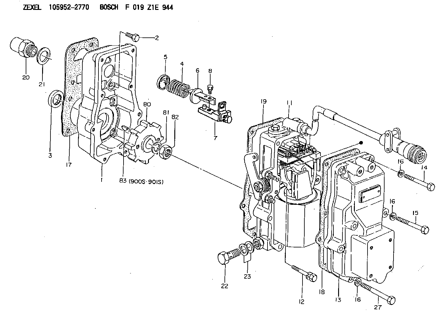
| 1. | [1] | 159560-0100 | GOVERNOR HOUSING |
| 2. | [8] | 139006-4100 | BLEEDER SCREW |
| 3. | [1] | 029621-7050 | PACKING RING |
| 4. | [1] | 159564-5200 | COILED SPRING |
| 5. | [1] | 159564-4000 | SLOTTED WASHER |
| 6. | [1] | 159564-4100 | SLOTTED WASHER |
| 7. | [1] | 159636-4520 | CONNECTOR |
| 7B. | [1] | 159636-4620 | CONNECTOR |
| 7C. | [1] | 159636-4720 | CONNECTOR |
| 8. | [1] | 020105-1240 | BLEEDER SCREW M5P0.8L12 |
| 11. | [1] | 159579-6220 | ACTUATOR |
| 12. | [2] | 020106-4040 | BLEEDER SCREW |
| 13. | [1] | 159561-0400 | GOVERNOR COVER |
| 14. | [4] | 010006-7040 | BLEEDER SCREW M6P1L70 |
| 15. | [2] | 010006-5540 | BLEEDER SCREW M6P1L55 4T |
| 16. | [8] | 014110-6440 | LOCKING WASHER |
| 16. | [8] | 014110-6440 | LOCKING WASHER |
| 16. | [8] | 014110-6440 | LOCKING WASHER |
| 17. | [1] | 154371-5600 | GASKET |
| 18. | [1] | 154390-0400 | GASKET |
| 19. | [1] | 154390-0500 | GASKET |
| 20. | [1] | 155404-3400 | CAP |
| 21. | [1] | 026524-3040 | GASKET |
| 22. | [1] | 029731-4680 | EYE BOLT |
| 23. | [2] | 029341-4130 | GASKET D20&13.8T2* |
| 27. | [2] | 139006-1300 | BLEEDER SCREW M6P1L76 |
| 80. | [1] | 159564-9200 | TOOTHED GEAR |
| 81. | [1] | 014111-2420 | LOCKING WASHER |
| 82. | [1] | 013031-2120 | UNION NUT |
| 83. | [1] | 025803-1310 | WOODRUFF KEY |
| 900S. | [1] | 025803-1310 | WOODRUFF KEY |
| 901S. | [1] | 025803-1610 | WOODRUFF KEY |
Include in #1:
106675-4800
as GOVERNOR
Cross reference number
Zexel num
Bosch num
Firm num
Name
Information:
2. Remove three nuts and washers (1).3. Move Peec unit (2) out of the way. (If so equipped). 4. Remove elbows (5) and pipes (7).5. Remove fuel line brackets (4).6. Remove bolts (6). Remove cover (3). 7. Remove elbows (10). Remove adapters (8) and adapters (9) from the aftercooler core. Remove bolts (11). 8. Move aftercooler core (12) toward the front of the engine and use two people to remove the aftercooler core from the lower aftercooler housing. The weight of the aftercooler core is approximately 29 kg (65 lb). Remove the O-ring seals from the aftercooler core extensions.Install Aftercooler
1. Install O-ring seals (13) on the aftercooler core extensions. Put clean engine oil or glycerin on the seals.2. Use two people to put aftercooler core (12) into position in the lower aftercooler housing. The weight of the aftercooler core is approximately 29 kg (65 lb). 3. Install bolts (11). Put clean engine oil or glycerin on O-ring seal (14) and in bores (15) and (16). 4. Put clean engine oil or glycerin on O-ring seals (17) and adapters (8) and (9). Install adapters (8) and (9) in the aftercooler core. 5. Install elbows (10). 6. Put cover (3) into position on the engine. Install bolts (6).7. Install fuel injection line brackets (4). Tighten bolts (20) to a torque of 4.5 1.1 N m (40 10 lb in).8. Put clean engine oil or glycerin on pipes (7). Install pipes (7) and elbows (5).9. Fill the cooling system with coolant. See Operation & Maintenance Manual for the proper procedure and levels.
1. Install O-ring seals (13) on the aftercooler core extensions. Put clean engine oil or glycerin on the seals.2. Use two people to put aftercooler core (12) into position in the lower aftercooler housing. The weight of the aftercooler core is approximately 29 kg (65 lb). 3. Install bolts (11). Put clean engine oil or glycerin on O-ring seal (14) and in bores (15) and (16). 4. Put clean engine oil or glycerin on O-ring seals (17) and adapters (8) and (9). Install adapters (8) and (9) in the aftercooler core. 5. Install elbows (10). 6. Put cover (3) into position on the engine. Install bolts (6).7. Install fuel injection line brackets (4). Tighten bolts (20) to a torque of 4.5 1.1 N m (40 10 lb in).8. Put clean engine oil or glycerin on pipes (7). Install pipes (7) and elbows (5).9. Fill the cooling system with coolant. See Operation & Maintenance Manual for the proper procedure and levels.