Information actuator
BOSCH
F 019 Z9E 338
f019z9e338
ZEXEL
105952-2762
1059522762
Rating:
Scheme ###:
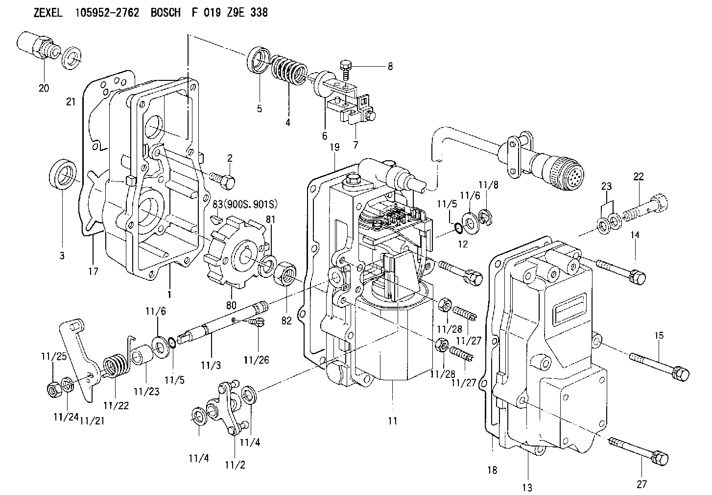
| 1. | [1] | 159560-0100 | GOVERNOR HOUSING |
| 2. | [8] | 139006-4100 | BLEEDER SCREW |
| 3. | [1] | 029621-7050 | PACKING RING |
| 4. | [1] | 159564-5200 | COILED SPRING |
| 5. | [1] | 159564-4000 | SLOTTED WASHER |
| 6. | [1] | 159635-8800 | SLOTTED WASHER |
| 7. | [1] | 159636-4521 | CONNECTOR |
| 7B. | [1] | 159636-4621 | CONNECTOR |
| 7C. | [1] | 159636-4721 | CONNECTOR |
| 8. | [1] | 020105-1240 | BLEEDER SCREW M5P0.8L12 |
| 11. | [1] | 159579-6221 | ACTUATOR |
| 11/2. | [1] | 159636-5020 | STRAP |
| 11/3. | [1] | 159563-1700 | LEVER SHAFT |
| 11/4. | [2] | 029311-0170 | SHIM |
| 11/4. | [2] | 029311-0170 | SHIM |
| 11/5. | [2] | 016500-0710 | O-RING |
| 11/5. | [2] | 016500-0710 | O-RING |
| 11/6. | [2] | 014011-0140 | PLAIN WASHER D22&10.5T1.6 |
| 11/6. | [2] | 014011-0140 | PLAIN WASHER D22&10.5T1.6 |
| 11/8. | [1] | 016010-0940 | LOCKING WASHER |
| 11/10. | [4] | 010206-2520 | HEX-SOCKET-HEAD CAP SCREW |
| 11/12. | [4] | 020105-2040 | BLEEDER SCREW M5P0.8L20 |
| 11/17. | [1] | 159568-5623 | CABLE SET |
| 11/18. | [2] | 020106-1440 | BLEEDER SCREW M6P1.0L14 |
| 11/19. | [1] | 131002-2700 | ADAPTOR |
| 11/21. | [1] | 159563-2300 | CONTROL LEVER |
| 11/22. | [1] | 159563-1600 | COILED SPRING |
| 11/23. | [1] | 159563-1800 | BUSHING |
| 11/24. | [1] | 014110-8440 | LOCKING WASHER |
| 11/25. | [1] | 013030-8140 | UNION NUT M8P1.25H5 |
| 11/26. | [1] | 159563-1000 | FLAT-HEAD SCREW |
| 11/27. | [2] | 155615-1700 | FLAT-HEAD SCREW |
| 11/27. | [2] | 155615-1700 | FLAT-HEAD SCREW |
| 11/28. | [2] | 029240-6010 | UNION NUT M6P1.0H5* |
| 11/28. | [2] | 029240-6010 | UNION NUT M6P1.0H5* |
| 11/29. | [1] | 159563-2701 | BRACKET |
| 11/32. | [2] | 020106-1440 | BLEEDER SCREW M6P1.0L14 |
| 11/40. | [4] | 014010-6140 | PLAIN WASHER D13&6.5T1 |
| 11/41. | [4] | 014110-6440 | LOCKING WASHER |
| 12. | [2] | 020106-4040 | BLEEDER SCREW |
| 13. | [1] | 159561-0400 | GOVERNOR COVER |
| 14. | [4] | 139006-9300 | BLEEDER SCREW |
| 15. | [2] | 139006-9200 | BLEEDER SCREW |
| 17. | [1] | 154371-5600 | GASKET |
| 18. | [1] | 154390-0400 | GASKET |
| 19. | [1] | 154390-0500 | GASKET |
| 20. | [1] | 155404-3400 | CAP |
| 21. | [1] | 026524-3040 | GASKET |
| 22. | [1] | 029731-4680 | EYE BOLT |
| 23. | [2] | 029341-4130 | GASKET D20&13.8T2* |
| 27. | [2] | 139006-9400 | BLEEDER SCREW |
| 80. | [1] | 159584-0200 | TOOTHED GEAR |
| 81. | [1] | 014111-2420 | LOCKING WASHER |
| 82. | [1] | 013031-2120 | UNION NUT |
| 83. | [1] | 025803-1310 | WOODRUFF KEY |
| 900S. | [1] | 025803-1310 | WOODRUFF KEY |
| 901S. | [1] | 025803-1610 | WOODRUFF KEY |
Include in #1:
106685-4322
as GOVERNOR
Cross reference number
Zexel num
Bosch num
Firm num
Name
105952-2762
F 019 Z9E 338
ACTUATOR
K
K
Information:
3. Remove turbo supply and drain lines (1). 4. Remove bolts (3) that holds bonnet (2) to engine block and torque converter oil cooler.5. Remove bolts (5), (6) and (7) (not shown) and remove cooler. Install in the reverse order. Fill cooling system with coolant. See the Operation & Maintenance Manual for the proper procedure and levels. Check the engine oil level. See the Operation & Maintenance Manual for the proper procedure and levels.End By:a. install oil filters and baseDisassemble Engine Oil Cooler & Bypass Valves
Start By:a. remove engine oil cooler and bypass valves 1. Remove bolts (1) to remove bypass valve assembly (3) from oil cooler (2). 2. Remove adapter (6) from the engine oil cooler. Remove O-ring seals (5) from the adapter.3. Remove bolts (4) to remove cover (7). Remove valves (9) and springs (8) from water line.4. Remove tube (10) from water lines. Remove O-ring seals (11) from the tube. 5. Clean the engine oil cooler tubes with a 3.2 mm (.125 in) diameter rod as shown.Assemble Engine Oil Cooler & Bypass Valves
1. Install new O-ring seals (1) on adapter (2). Install adapter (2) in the engine oil cooler.2. Install new O-ring seals (7) on tube (6). Install tube in water lines.3. Install valves (5) and springs (4) in the water line. Install cover (3) with the bolts (9) that hold it. 4. Install the bypass valve assembly on the engine oil cooler with the bolts (8) that hold it. Install the cover and bolts (9).End By:a. install engine oil cooler and bypass valves
Have questions with 105952-2762?
Group cross 105952-2762 ZEXEL
105952-2762
F 019 Z9E 338
ACTUATOR