Information actuator
BOSCH
F 019 Z2E 667
f019z2e667
ZEXEL
105952-2651
1059522651
Rating:
Scheme ###:
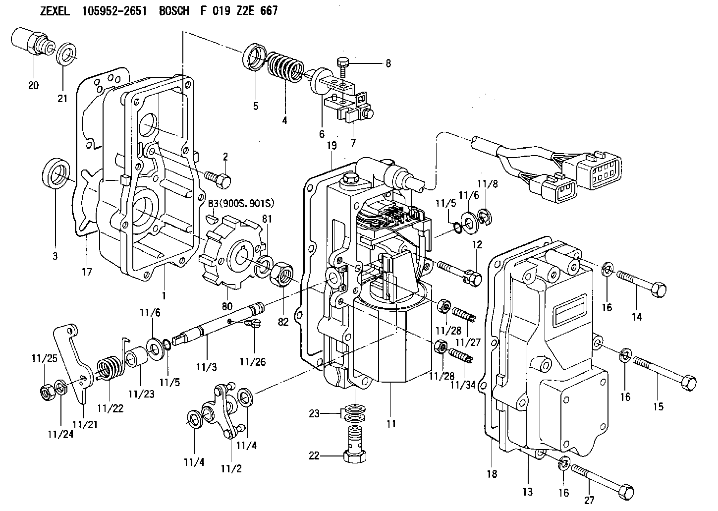
| 1. | [1] | 159560-0100 | GOVERNOR HOUSING |
| 2. | [8] | 139006-4100 | BLEEDER SCREW |
| 3. | [1] | 029621-7050 | PACKING RING |
| 4. | [1] | 159564-0000 | COILED SPRING |
| 5. | [1] | 159564-4000 | SLOTTED WASHER |
| 6. | [1] | 159564-4100 | SLOTTED WASHER |
| 7. | [1] | 159636-4520 | CONNECTOR |
| 7B. | [1] | 159636-4620 | CONNECTOR |
| 7C. | [1] | 159636-4720 | CONNECTOR |
| 8. | [1] | 020105-1240 | BLEEDER SCREW M5P0.8L12 |
| 11. | [1] | 159579-5621 | ACTUATOR |
| 11/1. | [1] | 159562-0820 | PLATE;GOV. |
| 11/2. | [1] | 159636-5020 | STRAP |
| 11/3. | [1] | 159563-1700 | LEVER SHAFT |
| 11/4. | [2] | 029311-0170 | SHIM |
| 11/4. | [2] | 029311-0170 | SHIM |
| 11/5. | [2] | 016500-0710 | O-RING |
| 11/5. | [2] | 016500-0710 | O-RING |
| 11/6. | [2] | 014011-0140 | PLAIN WASHER D22&10.5T1.6 |
| 11/6. | [2] | 014011-0140 | PLAIN WASHER D22&10.5T1.6 |
| 11/8. | [1] | 016010-0940 | LOCKING WASHER |
| 11/9. | [1] | 159585-0020 | LINEAR DC MOTOR |
| 11/10. | [4] | 020106-2540 | BLEEDER SCREW M6P1L25 |
| 11/11. | [1] | 159566-0720 | RACK SENSOR |
| 11/12. | [4] | 020105-2040 | BLEEDER SCREW M5P0.8L20 |
| 11/16. | [1] | 159565-2400 | LIP |
| 11/17. | [1] | 159568-9121 | CABLE SET |
| 11/18. | [2] | 020106-1440 | BLEEDER SCREW M6P1.0L14 |
| 11/19. | [1] | 134002-0200 | ADAPTOR |
| 11/21. | [1] | 159583-2800 | CONTROL LEVER |
| 11/22. | [1] | 159563-4800 | COILED SPRING |
| 11/23. | [1] | 159563-1800 | BUSHING |
| 11/24. | [1] | 014110-8440 | LOCKING WASHER |
| 11/25. | [1] | 013030-8140 | UNION NUT M8P1.25H5 |
| 11/26. | [1] | 159563-1000 | FLAT-HEAD SCREW |
| 11/27. | [1] | 155615-1700 | FLAT-HEAD SCREW |
| 11/28. | [2] | 029240-6010 | UNION NUT M6P1.0H5* |
| 11/28. | [2] | 029240-6010 | UNION NUT M6P1.0H5* |
| 11/29. | [1] | 159563-2701 | BRACKET |
| 11/30. | [1] | 479749-2400 | PULSE GENERATOR |
| 11/31. | [1] | 159592-0300 | UNION NUT |
| 11/32. | [2] | 020106-1440 | BLEEDER SCREW M6P1.0L14 |
| 11/34. | [1] | 159563-8400 | FLAT-HEAD SCREW |
| 12. | [2] | 020106-4040 | BLEEDER SCREW |
| 13. | [1] | 159561-0400 | GOVERNOR COVER |
| 14. | [4] | 010006-7040 | BLEEDER SCREW M6P1L70 |
| 15. | [2] | 010006-5540 | BLEEDER SCREW M6P1L55 4T |
| 16. | [8] | 014110-6440 | LOCKING WASHER |
| 16. | [8] | 014110-6440 | LOCKING WASHER |
| 16. | [8] | 014110-6440 | LOCKING WASHER |
| 17. | [1] | 154371-5600 | GASKET |
| 18. | [1] | 154390-0400 | GASKET |
| 19. | [1] | 154390-0500 | GASKET |
| 20. | [1] | 155404-3400 | CAP |
| 21. | [1] | 026524-3040 | GASKET |
| 22. | [1] | 029731-4680 | EYE BOLT |
| 23. | [2] | 029341-4130 | GASKET D20&13.8T2* |
| 27. | [2] | 139006-1300 | BLEEDER SCREW M6P1L76 |
| 80. | [1] | 159584-0000 | TOOTHED GEAR |
| 81. | [1] | 014111-2420 | LOCKING WASHER |
| 82. | [1] | 013031-2120 | UNION NUT |
| 83. | [1] | 025803-1310 | WOODRUFF KEY |
| 900S. | [1] | 025803-1310 | WOODRUFF KEY |
| 901S. | [1] | 025803-1610 | WOODRUFF KEY |
Cross reference number
Zexel num
Bosch num
Firm num
Name
Information:
1. Remove tachometer drive (3) from transfer pump cover (4).2. Remove bolts (1). Separate cover (4) and pump body (2). 3. Remove lip-type seal (6) from the cover. Remove plug (5), the seal, spring and plunger (bypass valve) from the cover. 4. Remove nut (10) from shaft (7). Remove gear (9) and key (11).5. Remove shaft (7) and gear (8) as a unit. Remove gear (8) from drive shaft (7) with a press.6. Remove idler gear (12). 7. Remove bushing (14), two lip-type seals and the bottom bearing from pump body (2).8. Remove check valve (13).Assemble Fuel Transfer Pump
1. Install bushing (4) in body (3) with Tooling (B). The bushing must be .80 .50 mm (.031 .020 in) below the (gear) surface of the body.2. Install the check valve in the body with Tooling (A).3. Install lip-type seal (5) with Tooling (C). Install the seal until it is 26.19 .13 mm (1.031 .005 in) from the bottom (drive gear) surface of body (3) and with the lip toward bushing (4) as shown.4. Install lip-type seal (6) with Tooling (D). Install the seal until it is 14.2 0.5 mm (.559 .020 in) from the bottom (drive gear) surface of body (3) and with the lip away from seal (5) as shown.5. Install bearing (7) in body (3) with Tooling (E). The bearing must be even with the bottom (drive gear) surface of the pump body. 6. Heat gear (8) to a maximum temperature of 315° C (600° F). Install gear (8) on shaft (11) until dimension (X) is 49.71 0.25 mm (1.957 .010 in).7. Install the drive shaft and gear in body (3). Install the key, gear (10) and nut (9). Tighten the nut to a torque of 30 7 N m (22 5 lb ft).8. Install idler gear (12) in body (3).9. Install lip-type seal (2) with Tooling (C). Install the seal until it is 22.61 .05 mm (.890 .002 in) from the top surface of cover (1) with the lip toward the inside as shown. 10. Install plunger (14) (bypass valve), spring (15) and seal and plug (13) in pump cover (1). Tighten plug (13) to a torque of 37 4 N m (27 3 lb ft).
Do not let the liquid gasket enter the pump during application or assembly.
11. Put 7M-7260 Liquid Gasket Material on the surface of cover (1). Install cover (1) on pump body (3). The drive shaft must turn freely after the bolts that hold the transfer pump together are tightened.12. Install the tachometer drive on cover (1).End By:a. install fuel transfer pump