Information actuator
BOSCH
F 019 Z3E 483
f019z3e483
ZEXEL
105952-2601
1059522601
Rating:
Scheme ###:
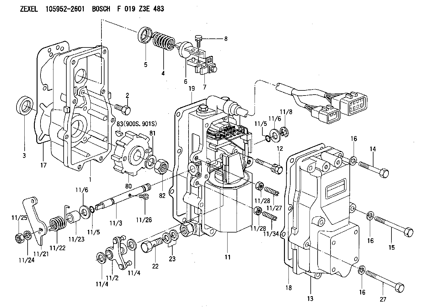
| 1. | [1] | 159560-0100 | GOVERNOR HOUSING |
| 2. | [8] | 139006-4100 | BLEEDER SCREW |
| 3. | [1] | 029621-7050 | PACKING RING |
| 4. | [1] | 159564-0000 | COILED SPRING |
| 5. | [1] | 159564-4000 | SLOTTED WASHER |
| 6. | [1] | 159564-4100 | SLOTTED WASHER |
| 7. | [1] | 159636-4520 | CONNECTOR |
| 7B. | [1] | 159636-4620 | CONNECTOR |
| 7C. | [1] | 159636-4720 | CONNECTOR |
| 8. | [1] | 020105-1240 | BLEEDER SCREW M5P0.8L12 |
| 11. | [1] | 159579-5421 | ACTUATOR |
| 11/1. | [1] | 159562-0720 | PLATE;GOV. |
| 11/2. | [1] | 159636-5020 | STRAP |
| 11/3. | [1] | 159563-1700 | LEVER SHAFT |
| 11/4. | [2] | 029311-0170 | SHIM |
| 11/4. | [2] | 029311-0170 | SHIM |
| 11/5. | [2] | 016500-0710 | O-RING |
| 11/6. | [2] | 014011-0140 | PLAIN WASHER D22&10.5T1.6 |
| 11/6. | [2] | 014011-0140 | PLAIN WASHER D22&10.5T1.6 |
| 11/6. | [2] | 014011-0140 | PLAIN WASHER D22&10.5T1.6 |
| 11/8. | [1] | 016010-0940 | LOCKING WASHER |
| 11/9. | [1] | 159585-0020 | LINEAR DC MOTOR |
| 11/10. | [4] | 020106-2540 | BLEEDER SCREW M6P1L25 |
| 11/11. | [1] | 159566-0720 | RACK SENSOR |
| 11/12. | [4] | 020105-2040 | BLEEDER SCREW M5P0.8L20 |
| 11/16. | [1] | 159565-2400 | LIP |
| 11/17. | [1] | 159568-8820 | CABLE SET |
| 11/18. | [2] | 020106-1440 | BLEEDER SCREW M6P1.0L14 |
| 11/19. | [1] | 131002-2700 | ADAPTOR |
| 11/21. | [1] | 159583-2800 | CONTROL LEVER |
| 11/22. | [1] | 159563-4800 | COILED SPRING |
| 11/23. | [1] | 159563-1800 | BUSHING |
| 11/24. | [1] | 014110-8440 | LOCKING WASHER |
| 11/25. | [1] | 013030-8140 | UNION NUT M8P1.25H5 |
| 11/26. | [1] | 159563-1000 | FLAT-HEAD SCREW |
| 11/27. | [1] | 155615-1700 | FLAT-HEAD SCREW |
| 11/28. | [2] | 029240-6010 | UNION NUT M6P1.0H5* |
| 11/28. | [2] | 029240-6010 | UNION NUT M6P1.0H5* |
| 11/29. | [1] | 159563-2701 | BRACKET |
| 11/30. | [1] | 479749-2400 | PULSE GENERATOR |
| 11/31. | [1] | 159592-0300 | UNION NUT |
| 11/32. | [2] | 020106-1440 | BLEEDER SCREW M6P1.0L14 |
| 11/34. | [1] | 159563-8400 | FLAT-HEAD SCREW |
| 12. | [2] | 020106-4040 | BLEEDER SCREW |
| 13. | [1] | 159561-0400 | GOVERNOR COVER |
| 14. | [4] | 010006-7040 | BLEEDER SCREW M6P1L70 |
| 15. | [2] | 010006-5540 | BLEEDER SCREW M6P1L55 4T |
| 16. | [8] | 014110-6440 | LOCKING WASHER |
| 16. | [8] | 014110-6440 | LOCKING WASHER |
| 16. | [8] | 014110-6440 | LOCKING WASHER |
| 17. | [1] | 154371-5600 | GASKET |
| 18. | [1] | 154390-0400 | GASKET |
| 19. | [1] | 154390-0500 | GASKET |
| 22. | [1] | 029731-4680 | EYE BOLT |
| 23. | [2] | 029341-4130 | GASKET D20&13.8T2* |
| 27. | [2] | 139006-1300 | BLEEDER SCREW M6P1L76 |
| 80. | [1] | 159584-0100 | TOOTHED GEAR |
| 81. | [1] | 014111-2420 | LOCKING WASHER |
| 82. | [1] | 013031-2120 | UNION NUT |
| 83. | [1] | 025803-1310 | WOODRUFF KEY |
| 900S. | [1] | 025803-1310 | WOODRUFF KEY |
| 901S. | [1] | 025803-1610 | WOODRUFF KEY |
Cross reference number
Zexel num
Bosch num
Firm num
Name
Information:
2. Turn the crankshaft until two of the pistons are at bottom center. Remove the nuts and bolts (1) from the connecting rods that are at bottom center. Remove connecting rod caps (2). Put identification marks on them for installation purposes.
Do not let the connecting rods hit the crankshaft or the bottom edge of the cylinder liners when the pistons are removed.
3. Push the connecting rods and pistons away from the crankshaft until the piston rings are out of the cylinder liners. Remove the two pistons from the engine.4. Keep each connecting rod cap with its respective connecting rod and piston. Put identification marks on each piston as to its location in the engine.5. Do Steps 1 through 4 for the removal of the remaining pistons.Install Pistons & Connecting Rods
1. Turn the crankshaft until the bearing journals for the pistons to be installed are at bottom center.2. Put clean engine oil on the crankshaft journals and on the inside of the cylinder liners. Put clean engine oil on the piston rings and the connecting rod bearings.3. Move the piston rings on the pistons until the ring openings are approximately 90° apart. 4. Put the piston in the cylinder liner with the "V" mark on the piston in alignment with the "V" mark on the cylinder block. Put Tool (A) in position on the cylinder block and compress the piston rings.5. Push the piston into the cylinder liner and out of the ring compressor. 6. Pull the connecting rod into position on the crankshaft as shown. Install connecting rod bolts (1) in the connecting rods.7. Put clean engine oil on the lower half of the connecting rod bearing. Put 2P2506 Thread Lubricant on the bolt threads and on the surfaces of the nuts that make contact with the connecting rod caps.
When the connecting rod caps are installed, make sure the number on the side of the cap is next to and respective with the number on the side of the connecting rod.
8. Install connecting rod caps (2) and the nuts that hold them. Tighten the nuts to a torque of 40 4 N m (30 3 lb ft). Put a mark on each nut as to its location. Tighten them 90° 5° more.9. Do Steps 1 through 8 for the remainder of the pistons.End By:a. install oil pumpb. install oil pan platec. install cylinder head assembly and spacer plateDisassemble Pistons & Connecting Rods
Start By:a. remove pistons and connecting rods 1. Remove the rings from the pistons with Tool (A). 2. Remove retaining ring (3), piston pin (1) and connecting rod (2) from the piston.3. Remove the bearings from the crankshaft end of the connecting rod.4. See Use Of Piston Pin Bearing Removal And Installation Tools, Special Instructions, Form No. SMHS7295-02 for more information about removal and installation of piston pin bearings. Be sure to remove the bearings from the crankshaft end of connecting rod.5. Heat the connecting rod in an oven to a temperature of 176