Information actuator
BOSCH
F 019 Z6E 000
f019z6e000
ZEXEL
105952-2182
1059522182
NISSAN-DIESEL
1910695507
1910695507

Rating:
Scheme ###:
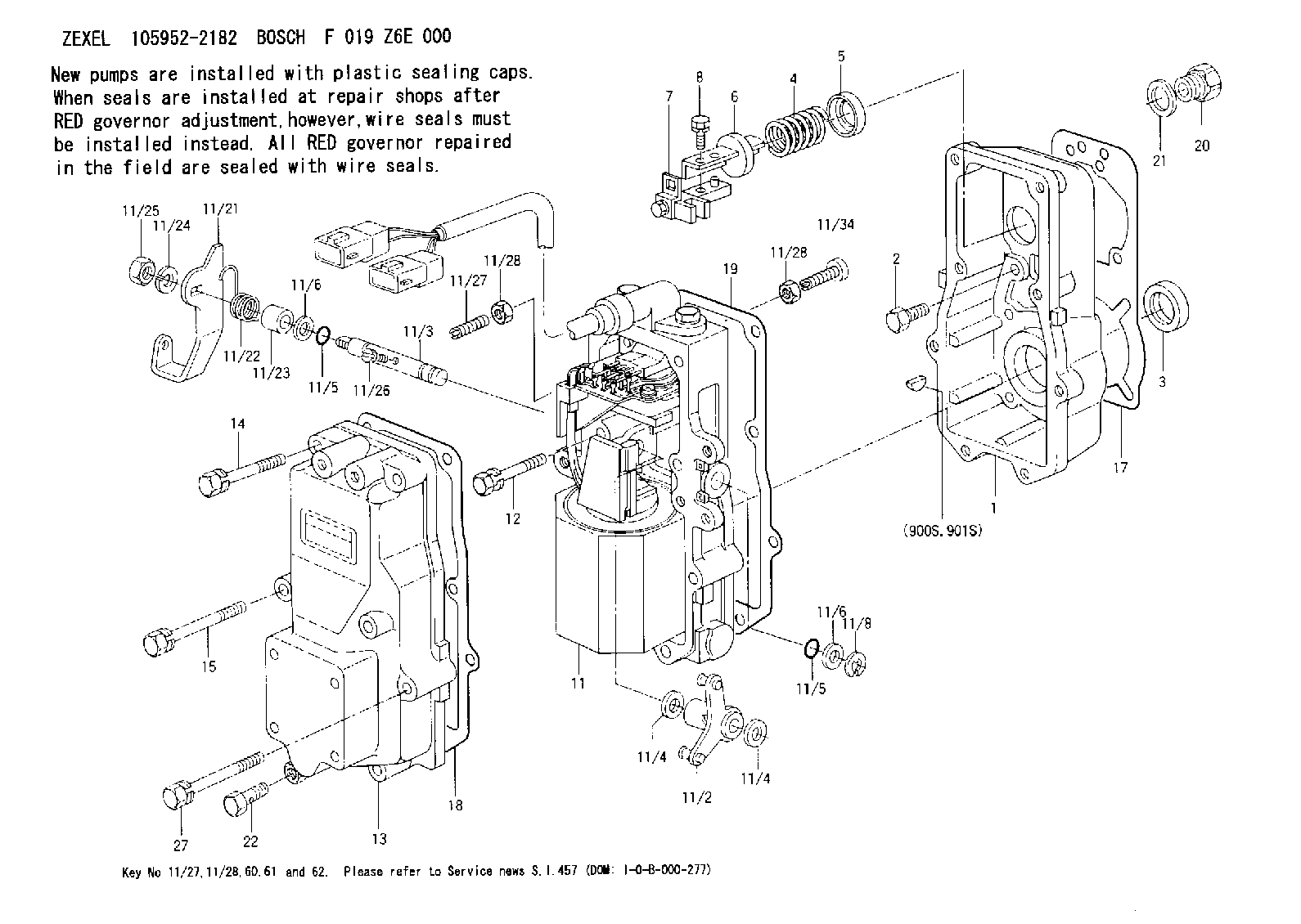
| 1. | [1] | 159560-0100 | GOVERNOR HOUSING |
| 2. | [8] | 139006-4100 | BLEEDER SCREW |
| 3. | [1] | 029621-7050 | PACKING RING |
| 4. | [1] | 159564-0000 | COILED SPRING |
| 5. | [1] | 159564-4000 | SLOTTED WASHER |
| 6. | [1] | 159564-4100 | SLOTTED WASHER |
| 7. | [1] | 159636-3121 | CONNECTOR |
| 7B. | [1] | 159636-3321 | CONNECTOR |
| 7C. | [1] | 159636-3521 | CONNECTOR |
| 8. | [1] | 020105-1240 | BLEEDER SCREW M5P0.8L12 |
| 11. | [1] | 159579-1422 | ACTUATOR |
| 11/2. | [1] | 159583-1020 | STRAP |
| 11/3. | [1] | 159563-1700 | LEVER SHAFT |
| 11/4. | [2] | 029311-0170 | SHIM |
| 11/4. | [2] | 029311-0170 | SHIM |
| 11/5. | [2] | 016500-0710 | O-RING |
| 11/5. | [2] | 016500-0710 | O-RING |
| 11/6. | [2] | 014011-0140 | PLAIN WASHER D22&10.5T1.6 |
| 11/6. | [2] | 014011-0140 | PLAIN WASHER D22&10.5T1.6 |
| 11/8. | [1] | 016010-0940 | LOCKING WASHER |
| 11/10. | [4] | 139006-9100 | BLEEDER SCREW |
| 11/12. | [4] | 020105-2040 | BLEEDER SCREW M5P0.8L20 |
| 11/18. | [2] | 020106-1440 | BLEEDER SCREW M6P1.0L14 |
| 11/19. | [1] | 134002-0200 | ADAPTOR |
| 11/21. | [1] | 159563-7120 | CONTROL LEVER |
| 11/22. | [1] | 159563-4800 | COILED SPRING |
| 11/23. | [1] | 159563-1800 | BUSHING |
| 11/24. | [1] | 014110-8440 | LOCKING WASHER |
| 11/25. | [1] | 013030-8140 | UNION NUT M8P1.25H5 |
| 11/26. | [1] | 159563-1000 | FLAT-HEAD SCREW |
| 11/27. | [1] | 139006-9800 | FLAT-HEAD SCREW |
| 11/28. | [2] | 013020-6040 | UNION NUT M6P1H5 |
| 11/28. | [2] | 013020-6040 | UNION NUT M6P1H5 |
| 11/34. | [1] | 139006-9900 | FLAT-HEAD SCREW |
| 12. | [2] | 020106-4040 | BLEEDER SCREW |
| 13. | [1] | 159561-0400 | GOVERNOR COVER |
| 14. | [4] | 139006-9300 | BLEEDER SCREW |
| 15. | [2] | 139006-9200 | BLEEDER SCREW |
| 17. | [1] | 154371-5600 | GASKET |
| 18. | [1] | 154390-0400 | GASKET |
| 19. | [1] | 154390-0500 | GASKET |
| 20. | [1] | 155404-3400 | CAP |
| 21. | [1] | 026524-3040 | GASKET |
| 22. | [1] | 029731-4680 | EYE BOLT |
| 27. | [2] | 139006-9400 | BLEEDER SCREW |
| 60. | [2] | 013020-6040 | UNION NUT M6P1H5 |
| 900S. | [1] | 025803-1310 | WOODRUFF KEY |
| 901S. | [1] | 025803-1610 | WOODRUFF KEY |
Include in #1:
106671-5762
as GOVERNOR
Cross reference number
Zexel num
Bosch num
Firm num
Name
105952-2182
F 019 Z6E 000
1910695507 NISSAN-DIESEL
ACTUATOR
K
K
Information:
3306 New Scroll Fuel System (NSFS) Hydraulic Actuator
The variable power actuator is mounted to the rear of the governor housing, where the shutoff solenoid is normally mounted. The actuator rod may be in one of two positions -- extended or retracted. The extended position limits the fuel rack travel to the lower power fuel setting. The retracted position allows the fuel rack to travel to the higher power fuel setting. By limiting the travel of the fuel rack, the fuel being injected into the engine is controlled. Fuel being injected into the engine determines the output power of the engine. The position of the actuator rod is determined by the gear engaged in the transmission of the applicable vehicle.High Power Range
Typical Variable Power Arrangement
1. Manifold. 2. Solenoid control valve. 3. Variable power actuator. 4. Governor control lever. 5. Transmission. 6. Switch.An electric switch (6) is mounted in the transmission (5). The transmission (5) is shifted into a gear where the higher power range is allowed. A transmission interlock pin causes the normally open switch (6) to close. When switch (6) is closed, it energizes solenoid control valve (2). The energized solenoid control valve (2) allows engine lube oil (under normal engine lube oil pressure) to flow through manifold (1) and into actuator (3).
Governor And Actuator
3. Actuator. 7. Oil inlet/outlet port. 11. Governor servo valve. 12. Lever. 13. Governor control shaft. 14. Actuator rod.The engine oil coming in port (7) compresses spring (15) and moves actuator rod (14) to the RETRACTED position. The RETRACTED actuator rod (14) allows the fuel rack more travel in the FUEL ON direction by a mechanical linkage through the governor servo valve (11) and lever (12). The fuel rack travel is now limited by the fuel setting screw.The actuator rod (14) will remain in the RETRACTED position as long as solenoid control valve (2) is energized. A light on the operator's console indicates when the engine is operating in the higher power range.
Governor And Variable Power Actuator (Retracted Position7. Oil inlet/outlet port.8. Washered adjusting
Have questions with 105952-2182?
Group cross 105952-2182 ZEXEL
Mitsubishi
Nissan-Diesel
Nissan-Diesel
Nissan-Diesel
Nissan-Diesel
105952-2182
F 019 Z6E 000
1910695507
ACTUATOR