Information actuator
BOSCH
9 420 611 892
9420611892
ZEXEL
105952-2140
1059522140
Rating:
Scheme ###:
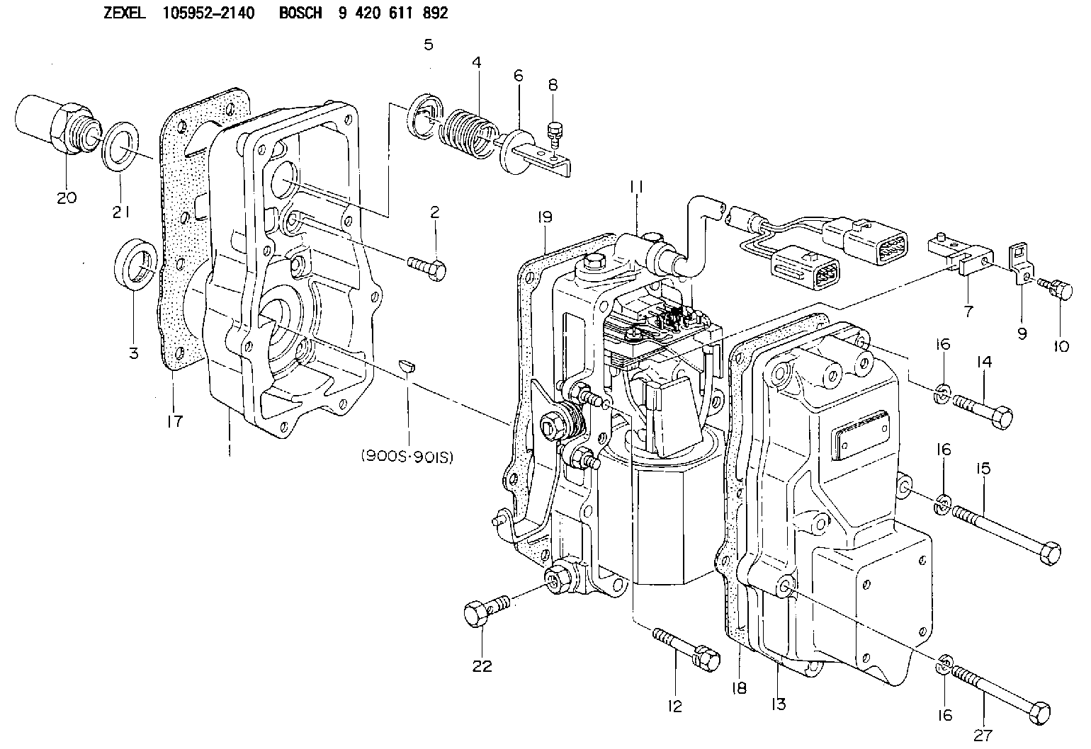
| 1. | [1] | 159560-0100 | GOVERNOR HOUSING |
| 2. | [8] | 139006-4100 | BLEEDER SCREW |
| 3. | [1] | 029621-7050 | PACKING RING |
| 4. | [1] | 159564-0000 | COILED SPRING |
| 5. | [1] | 159564-4000 | SLOTTED WASHER |
| 6. | [1] | 159564-4100 | SLOTTED WASHER |
| 7. | [1] | 159564-7321 | CONNECTOR |
| 8. | [1] | 020105-1240 | BLEEDER SCREW M5P0.8L12 |
| 9. | [1] | 159564-0501 | PLATE |
| 9B. | [1] | 159564-6500 | PLATE |
| 9C. | [1] | 159584-5200 | PLATE |
| 10. | [1] | 020105-1240 | BLEEDER SCREW M5P0.8L12 |
| 11. | [1] | 159579-1220 | ACTUATOR |
| 12. | [2] | 020106-4040 | BLEEDER SCREW |
| 13. | [1] | 159561-0400 | GOVERNOR COVER |
| 14. | [4] | 010006-7040 | BLEEDER SCREW M6P1L70 |
| 15. | [2] | 010006-5540 | BLEEDER SCREW M6P1L55 4T |
| 16. | [8] | 014110-6440 | LOCKING WASHER |
| 16. | [8] | 014110-6440 | LOCKING WASHER |
| 16. | [8] | 014110-6440 | LOCKING WASHER |
| 17. | [1] | 154371-5600 | GASKET |
| 18. | [1] | 154390-0400 | GASKET |
| 19. | [1] | 154390-0500 | GASKET |
| 20. | [1] | 155404-3400 | CAP |
| 21. | [1] | 026524-3040 | GASKET |
| 22. | [1] | 029731-4680 | EYE BOLT |
| 27. | [2] | 139006-1300 | BLEEDER SCREW M6P1L76 |
| 900S. | [1] | 025803-1310 | WOODRUFF KEY |
| 901S. | [1] | 025803-1610 | WOODRUFF KEY |
Include in #1:
106671-5750
as GOVERNOR
Cross reference number
Zexel num
Bosch num
Firm num
Name
Information:
7N9720 Alternator 24V 35A (Bosch Number 0-122-469-001); 9G9538 Alternator 24V 50A (Bosch Number 0-122-469-002)
7N9720 AlternatorThe solid state regulator used with the Bosch Alternator is totally enclosed and non-adjustable. If the rate of charge is not correct a replacement of the regulator is necessary.9G4574 24V 35A (Nippondenso Number 100211-0860); 6T7223 24V 50A (Nippondenso Number 100211-0890)
9G4574 AlternatorNo adjustment can be made to change the rate of charge on the alternator regulator. If rate of charge is not correct, a replacement of the regulator is necessary.2P1204 24V 15A (Prestolite Number ANB-7004)
Prestolite Alternator Regulator
1. Adjustment screw. 2. High output position. 3. Green wire to field terminal of alternator. 4. Low output position. 5. Orange wire to field supply terminal.The regulator components are sealed in an insulation of epoxy. The regulator is an electronic component with no moving parts (solid state) and has an adjustment screw (1) on the back. This voltage adjustment screw is used to meet different needs of operation at different times of the year. To increase or decrease by .5 volts from the normal (N) setting, remove the regulator and change the position of the adjustment screw and pointer. Move the adjustment screw (1) and pointer to "H" position (2) to increase the voltage. Move adjustment screw (1) and pointer to "L" position (4) to decrease the voltage.Starting System
Use the multimeter in the DCV range to find starting system components which do not function.Move the start control switch to activate the starter solenoid. Starter solenoid operation can be heard as the pinion of the starter motor is engaged with the ring gear on the engine flywheel.If the solenoid for the starter motor will not operate, it is possible that the current from the battery did not get to the solenoid. Fasten one lead of the multimeter to the connection (terminal) for the battery cable on the solenoid. Put the other lead to a good ground. A zero reading is an indication that there is a broken circuit from the battery. More testing is necessary when there is a voltage reading on the multimeter.The solenoid operation also closes the electric circuit to the motor. Connect one lead of the multimeter to the solenoid connection (terminal) that is fastened to the motor. Put the other lead to a good ground. Activate the starter solenoid and look at the multimeter. A reading of battery voltage shows the problem is in the motor. The motor must be removed for further testing. A zero reading on the multimeter shows that the solenoid contacts do not close. This is an indication of the need for repair to the solenoid or an adjustment to be made to the starter pinion clearance.Make a test with one multimeter lead fastened to the connection (terminal) for the small wire at the solenoid and the other lead to the ground. Look at the multimeter and activate the starter solenoid. A voltage reading shows that the problem is in the solenoid. A zero reading is an indication that the problem is