Information actuator
BOSCH
9 420 610 598
9420610598
ZEXEL
105952-1920
1059521920
NISSAN-DIESEL
1910697010
1910697010
Rating:
Scheme ###:
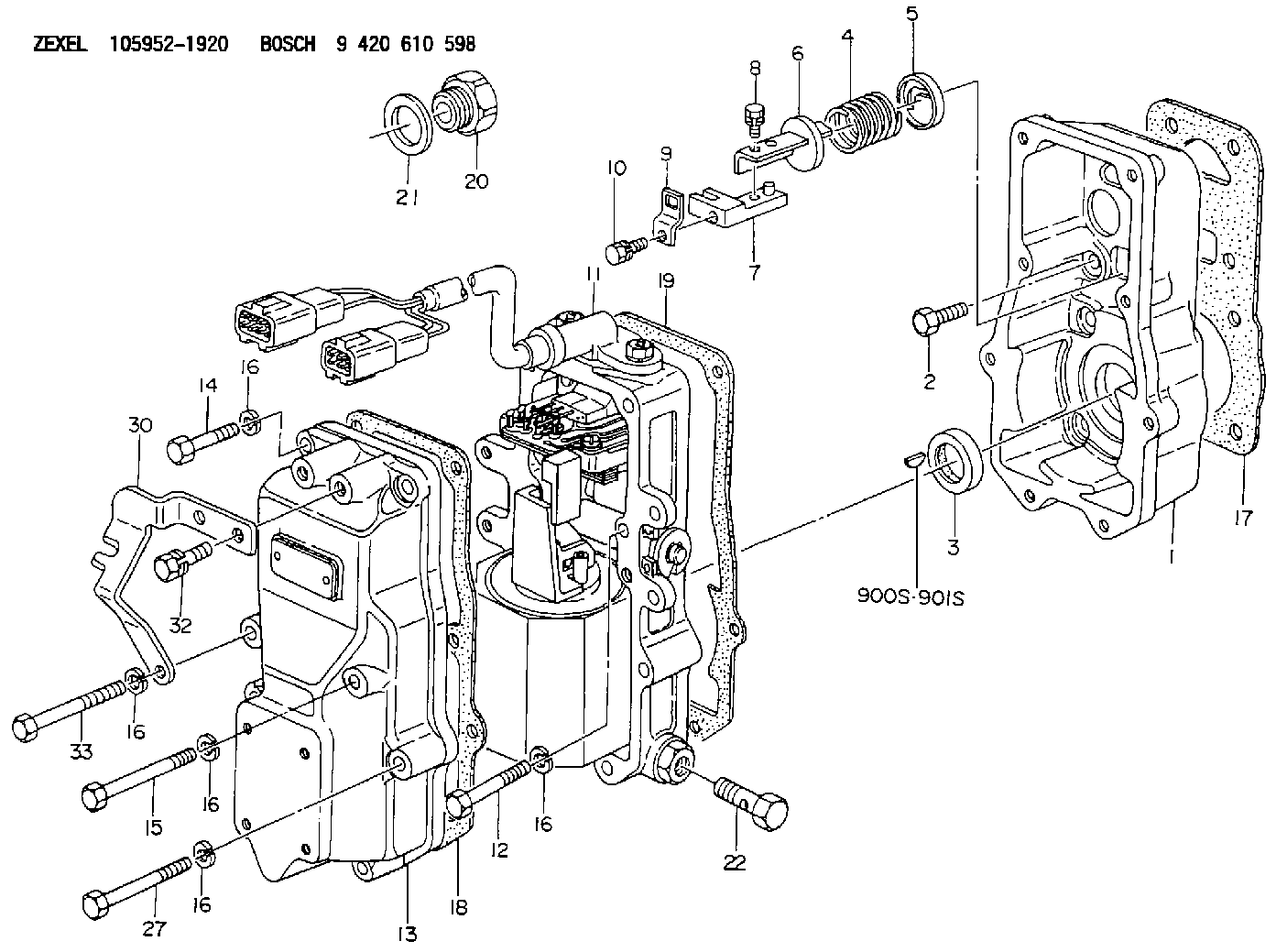
| 1. | [1] | 159560-0100 | GOVERNOR HOUSING |
| 2. | [8] | 139006-4100 | BLEEDER SCREW |
| 3. | [1] | 029621-7050 | PACKING RING |
| 4. | [1] | 159564-5200 | COILED SPRING |
| 5. | [1] | 159564-4000 | SLOTTED WASHER |
| 6. | [1] | 159564-4100 | SLOTTED WASHER |
| 7. | [1] | 159564-7321 | CONNECTOR |
| 8. | [1] | 020105-1240 | BLEEDER SCREW M5P0.8L12 |
| 9. | [1] | 159564-0501 | PLATE |
| 9B. | [1] | 159564-6500 | PLATE |
| 9C. | [1] | 159584-5200 | PLATE |
| 10. | [1] | 020105-1240 | BLEEDER SCREW M5P0.8L12 |
| 11. | [1] | 159569-9620 | ACTUATOR |
| 12. | [2] | 020106-4040 | BLEEDER SCREW |
| 13. | [1] | 159561-0400 | GOVERNOR COVER |
| 14. | [4] | 010006-7040 | BLEEDER SCREW M6P1L70 |
| 15. | [1] | 010006-5540 | BLEEDER SCREW M6P1L55 4T |
| 16. | [8] | 014110-6440 | LOCKING WASHER |
| 16. | [8] | 014110-6440 | LOCKING WASHER |
| 16. | [8] | 014110-6440 | LOCKING WASHER |
| 16. | [8] | 014110-6440 | LOCKING WASHER |
| 16. | [8] | 014110-6440 | LOCKING WASHER |
| 17. | [1] | 154371-5600 | GASKET |
| 18. | [1] | 154390-0400 | GASKET |
| 19. | [1] | 154390-0500 | GASKET |
| 20. | [1] | 155404-1700 | CAP |
| 21. | [1] | 026524-3040 | GASKET |
| 22. | [1] | 029731-4680 | EYE BOLT |
| 27. | [2] | 139006-1300 | BLEEDER SCREW M6P1L76 |
| 30. | [1] | 159584-1100 | BRACKET |
| 32. | [2] | 020006-1240 | BLEEDER SCREW M6P1L12 4T |
| 33. | [1] | 159563-2400 | BLEEDER SCREW |
| 900S. | [1] | 025803-1310 | WOODRUFF KEY |
| 901S. | [1] | 025803-1610 | WOODRUFF KEY |
Cross reference number
Zexel num
Bosch num
Firm num
Name
105952-1920
9 420 610 598
1910697010 NISSAN-DIESEL
ACTUATOR
K 14JT ACTUATOR GOV
K 14JT ACTUATOR GOV
Information:
2. Disconnect the fuel lines from fuel transfer pump (1).3. Remove two bolts (2) and fuel transfer pump (1). 4. Be sure O-ring seal (3) is in position on the fuel transfer pump and put clean oil on the O-ring seal.5. Put the fuel transfer pump in position on the fuel injection pump and install the two bolts that hold it in place.6. Connect the fuel lines to the fuel transfer pump.7. Open the fuel shutoff valve at the fuel tank.Disassemble Fuel Transfer Pump
start by:a) remove fuel transfer pump
Cover (2) is under spring tension.
1. Carefully remove bolts (1) and cover (2) from the fuel transfer pump. 2. Remove spring (3), valve (4) and O-ring seals (5) from the cover. 3. Remove springs (6) and (7) from the pump housing. 4. Remove sleeve (8) from the pump housing. 5. Remove sleeve (12), piston (16), O-ring seal (11) and piston (9) from sleeve (8). Remove plate (15), valve (10) and seal (14) from piston (9). Remove O-ring seal (13) from sleeve (8). 6. Remove O-ring seal (17) from the pump housing. 7. Push guide (18) through the pump housing and remove guides (23) and (18) together. Remove rod (20), guide (23), O-ring seal (19) and tappet (21) from guide (18). Remove ring (22) from tappet (21). 8. Remove connector (24), valve (26) and seal (25) from the pump housing. 9. Remove plug (30), spring (28), valve (29) and seal (27) from the pump housing.Assemble Fuel Transfer Pump
1. Clean all parts and be sure all passage are open. 2. Be sure the O-ring seal is in position on plug (4) and put 4L7464 Silicone Grease on the O-ring seal. Valves (2 and 6) must be installed as shown for the pump to work correctly.3. Install seal (1), valve (2), spring (3) and plug (4) in the pump housing as shown. Tighten plug (4) to a torque of 20 7 N m (15 5 lb.ft.). 4. Be sure the O-ring seal is in position on connector (7) and put 4L7464 Silicone Grease on the O-ring seal.5. Install seal (5), valve (6) and connector (7) in the pump housing as shown. Tighten connector (7) to a torque of 55 10 N m (40 7 lb.ft.). 6. Install the ring on tappet (8). Install tappet (8), O-ring seal (12), guide (9) and rod (10) in guide (11). Put 4L7464 Silicone Grease on O-ring seal (12). Install guides (11) and (9) as a unit in the pump housing as shown. 7. Install O-ring seal (13) in the pump housing and put 4L7464 Silicone Grease on the O-ring seal. 8. Install seal (15), valve (19) and plate (16) in piston (14) as shown. Install piston (14), O-ring seal (17), piston (20) and guide (21) in guide (18) as shown. Install the O-ring seal on guide (18) and put 4L7464 Silicone Grease on O-ring seal (17) and the O-ring seal on guide (18). 9. Install guide (18) in the pump housing as shown.
Have questions with 105952-1920?
Group cross 105952-1920 ZEXEL
Isuzu
Mitsubishi
Nissan-Diesel
105952-1920
9 420 610 598
1910697010
ACTUATOR