Information actuator
BOSCH
9 420 610 984
9420610984
ZEXEL
105952-1730
1059521730
Rating:
Scheme ###:
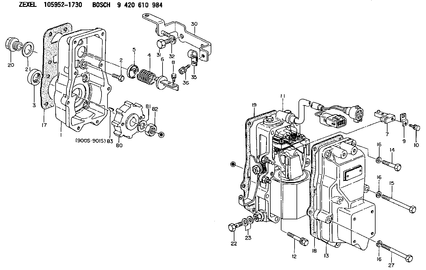
| 1. | [1] | 159560-0900 | GOVERNOR HOUSING |
| 2. | [8] | 139006-4100 | BLEEDER SCREW |
| 3. | [1] | 029621-7050 | PACKING RING |
| 4. | [1] | 159564-0000 | COILED SPRING |
| 5. | [1] | 159564-4000 | SLOTTED WASHER |
| 6. | [1] | 159564-4100 | SLOTTED WASHER |
| 7. | [1] | 159564-7321 | CONNECTOR |
| 8. | [1] | 020105-1240 | BLEEDER SCREW M5P0.8L12 |
| 9. | [1] | 159564-0501 | PLATE |
| 9B. | [1] | 159564-6500 | PLATE |
| 9C. | [1] | 159584-5200 | PLATE |
| 10. | [1] | 020105-1240 | BLEEDER SCREW M5P0.8L12 |
| 11. | [1] | 159569-7820 | ACTUATOR |
| 12. | [2] | 020106-4040 | BLEEDER SCREW |
| 13. | [1] | 159561-0400 | GOVERNOR COVER |
| 14. | [4] | 010006-7040 | BLEEDER SCREW M6P1L70 |
| 15. | [2] | 010006-5540 | BLEEDER SCREW M6P1L55 4T |
| 16. | [8] | 014110-6440 | LOCKING WASHER |
| 16. | [8] | 014110-6440 | LOCKING WASHER |
| 16. | [8] | 014110-6440 | LOCKING WASHER |
| 17. | [1] | 159566-0400 | GASKET |
| 18. | [1] | 154390-0400 | GASKET |
| 19. | [1] | 154390-0500 | GASKET |
| 20. | [1] | 153021-6300 | CAP |
| 21. | [1] | 026524-3040 | GASKET |
| 22. | [1] | 029731-4680 | EYE BOLT |
| 23. | [2] | 139514-0300 | GASKET |
| 27. | [2] | 139006-1300 | BLEEDER SCREW M6P1L76 |
| 30. | [1] | 159584-1320 | BRACKET |
| 31. | [2] | 010010-2040 | BLEEDER SCREW M10P1.5L20 |
| 32. | [2] | 014111-0440 | LOCKING WASHER |
| 35. | [1] | 159564-7100 | CLAMPING BAND |
| 36. | [1] | 020106-1640 | BLEEDER SCREW M6P1.0L14 |
| 80. | [1] | 159584-0000 | TOOTHED GEAR |
| 81. | [1] | 014111-2420 | LOCKING WASHER |
| 82. | [1] | 013031-2120 | UNION NUT |
| 83. | [1] | 025803-1310 | WOODRUFF KEY |
| 900S. | [1] | 025803-1310 | WOODRUFF KEY |
| 901S. | [1] | 025803-1610 | WOODRUFF KEY |
Cross reference number
Zexel num
Bosch num
Firm num
Name
Information:
Delco-Remy Alternator
(1) Regulator. (2) Roller bearing. (3) Stator winding. (4) Ball bearing. (5) Rectifier bridge. (6) Field winding. (7) Rotor assembly. (8) Fan.Alternator (Bosch)
The alternator is driven by V-belts from the crankshaft pulley. This alternator is a three phase, self-rectifying charging unit. The regulator is part of the alternator.
Bosch Alternator
(1) Fan. (2) Stator winding. (3) Field winding. (4) Regulator. (5) Ball bearing. (6) Roller bearing. (7) Rotor. (8) Rectifier assembly.This alternator design has no need for slip rings or brushes, and the only part that has movement is the rotor assembly. All conductors that carry current are stationary. The conductors are: the field winding, stator windings, six rectifying diodes, and the regulator circuit components.The rotor assembly has many magnetic poles like fingers with air space between each opposite pole. The poles have residual magnetism (like permanent magnets) that produce a small amount of magnet-like lines of force (magnetic field) between the poles. As the rotor assembly begins to turn between the field winding and the stator windings, a small amount of alternating current (AC) is produced in the stator windings from the small magnetic lines of force made by the residual magnetism of the poles. This AC current is changed to direct current (DC) when it passes through the diodes of the rectifier bridge. Most of this current goes to charge the battery and to supply the low amperage circuit, and the remainder is sent to the field windings. The DC current flow through the field windings (wires around an iron core) now increases the strength of the magnetic lines of force. These stronger lines of force now increase the amount of AC current produced in the stator windings. The increased speed of the rotor assembly also increases the current and voltage output of the alternator.The voltage regulator is a solid state (transistor, stationary parts) electronic switch. It feels the voltage in the system and switches on and off many times a second to control the field current (DC current to the field windings) for the alternator to make the needed voltage output.Alternator (Nippondenso)
The alternator is driven by a V-belt from the crankshaft pulley. The only part in the alternator which has movement is rotor assembly (9). Rotor assembly (9) is held in position by a ball bearing at each end of rotor shaft (8).The alternator is made up of a frame (3) on the drive end, rotor assembly (9), stator assembly (5), rectifier assembly (11), brushes (7) and holder assembly, slip rings (13), rear end frame (12) and regulator (6). Drive pulley (1) has a fan (2) for heat removal by the movement of air through the alternator.
Alternator Schematic (With Regulator Attached)
(1) Pulley. (2) Fan. (3) Drive end frame. (4) Stator coils. (5) Stator assembly. (6) Regulator. (7) Brushes. (8) Rotor shaft. (9) Rotor assembly. (10) Field windings. (11) Rectifier assembly. (12) Rear end frame. (13) Slip rings.Rotor assembly (9) has field windings (10) (wires around an iron core) which make magnetic lines of force when direct