Information actuator
BOSCH
9 420 614 432
9420614432
ZEXEL
105952-1571
1059521571
MITSUBISHI
ME742629
me742629
Rating:
Scheme ###:
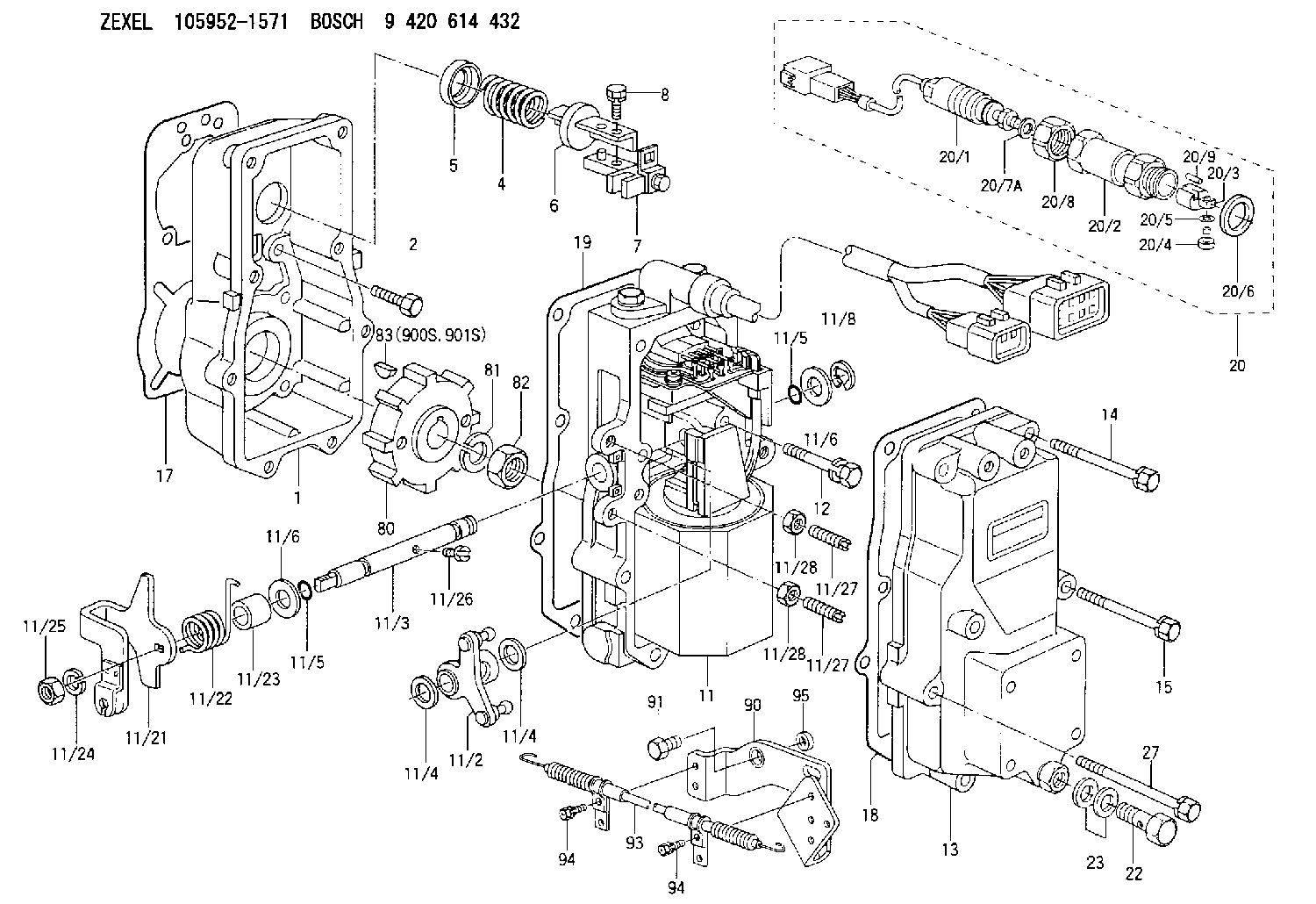
| 1. | [1] | 159560-0900 | GOVERNOR HOUSING |
| 2. | [8] | 139006-4100 | BLEEDER SCREW |
| 4. | [1] | 159564-0000 | COILED SPRING |
| 5. | [1] | 159564-4000 | SLOTTED WASHER |
| 6. | [1] | 159564-4100 | SLOTTED WASHER |
| 7. | [1] | 159636-3121 | CONNECTOR |
| 7B. | [1] | 159636-3321 | CONNECTOR |
| 7C. | [1] | 159636-3521 | CONNECTOR |
| 8. | [1] | 020105-1240 | BLEEDER SCREW M5P0.8L12 |
| 9. | [1] | 159564-0501 | PLATE |
| 9B. | [1] | 159564-6500 | PLATE |
| 9C. | [1] | 159584-5200 | PLATE |
| 10. | [1] | 020105-1240 | BLEEDER SCREW M5P0.8L12 |
| 11. | [1] | 159569-6320 | ACTUATOR |
| 11/2. | [1] | 159583-1020 | STRAP |
| 11/3. | [1] | 159563-1700 | LEVER SHAFT |
| 11/4. | [2] | 029311-0170 | SHIM |
| 11/4. | [2] | 029311-0170 | SHIM |
| 11/5. | [2] | 016500-0710 | O-RING |
| 11/5. | [2] | 016500-0710 | O-RING |
| 11/6. | [2] | 014011-0140 | PLAIN WASHER D22&10.5T1.6 |
| 11/6. | [2] | 014011-0140 | PLAIN WASHER D22&10.5T1.6 |
| 11/8. | [1] | 016010-0940 | LOCKING WASHER |
| 11/10. | [4] | 020106-2540 | BLEEDER SCREW M6P1L25 |
| 11/12. | [4] | 020105-2040 | BLEEDER SCREW M5P0.8L20 |
| 11/18. | [2] | 020106-1440 | BLEEDER SCREW M6P1.0L14 |
| 11/21. | [1] | 159563-9120 | CONTROL LEVER |
| 11/22. | [1] | 159563-1600 | COILED SPRING |
| 11/23. | [1] | 159563-1800 | BUSHING |
| 11/24. | [1] | 014110-8440 | LOCKING WASHER |
| 11/25. | [1] | 013030-8140 | UNION NUT M8P1.25H5 |
| 11/26. | [1] | 159563-1000 | FLAT-HEAD SCREW |
| 11/27. | [2] | 155615-1700 | FLAT-HEAD SCREW |
| 11/27. | [2] | 155615-1700 | FLAT-HEAD SCREW |
| 11/28. | [2] | 029240-6010 | UNION NUT M6P1.0H5* |
| 11/28. | [2] | 029240-6010 | UNION NUT M6P1.0H5* |
| 11/32. | [2] | 020106-1440 | BLEEDER SCREW M6P1.0L14 |
| 12. | [2] | 020106-4040 | BLEEDER SCREW |
| 13. | [1] | 159561-0920 | GOVERNOR COVER |
| 14. | [4] | 139006-9300 | BLEEDER SCREW |
| 15. | [2] | 139006-9200 | BLEEDER SCREW |
| 16. | [8] | 014110-6440 | LOCKING WASHER |
| 17. | [1] | 159566-0400 | GASKET |
| 18. | [1] | 154390-0400 | GASKET |
| 19. | [1] | 154390-0500 | GASKET |
| 20. | [1] | 154611-4820 | RACK SENSOR ASSY |
| 20/1. | [1] | 479742-8820 | RACK SENSOR |
| 20/2. | [1] | 154614-4800 | JOINT CONNECTION |
| 20/3. | [1] | 154614-3200 | BLOCK |
| 20/4. | [1] | 010234-1040 | HEX-SOCKET-HEAD CAP SCREW |
| 20/5. | [1] | 014110-4440 | LOCKING WASHER |
| 20/6. | [1] | 026524-3040 | GASKET |
| 20/7A. | [0] | 029310-6220 | SHIM D11.5&6.5T0.10 |
| 20/7B. | [0] | 029310-6230 | SHIM D11.5&6.5T0.20 |
| 20/7C. | [0] | 029310-6240 | SHIM D11.5&6.5T0.25 |
| 20/7D. | [0] | 029310-6260 | SHIM D11.5&6.4T1.00 |
| 20/7E. | [0] | 029310-6270 | SHIM D11.5&6.4T1.20 |
| 20/7F. | [0] | 029310-6280 | SHIM D11.5&6.4T1.50 |
| 20/8. | [1] | 154614-1900 | UNION NUT |
| 20/9. | [1] | 154614-3300 | BEARING PIN |
| 22. | [1] | 153556-4800 | EYE BOLT |
| 23. | [2] | 029331-2120 | GASKET |
| 27. | [2] | 139006-9400 | BLEEDER SCREW |
| 80. | [1] | 159584-0700 | TOOTHED GEAR |
| 81. | [1] | 014111-2420 | LOCKING WASHER |
| 82. | [1] | 013031-2120 | UNION NUT |
| 83. | [1] | 025803-1310 | WOODRUFF KEY |
| 90. | [1] | 159563-9520 | BRACKET |
| 91. | [2] | 156633-4700 | BLEEDER SCREW |
| 93. | [1] | 159563-9220 | WIRE |
| 94. | [4] | 020106-1040 | BLEEDER SCREW M6P1L12 |
| 94. | [4] | 020106-1040 | BLEEDER SCREW M6P1L12 |
| 95. | [1] | 159235-0300 | SPACER BUSHING |
| 900S. | [1] | 025803-1310 | WOODRUFF KEY |
| 901S. | [1] | 025803-1610 | WOODRUFF KEY |
Cross reference number
Zexel num
Bosch num
Firm num
Name
105952-1571
9 420 614 432
ME742629 MITSUBISHI
ACTUATOR
K
K
Information:
Reassembly and adjustment (2-spring nozzle)
Adjust while assembling the parts by the following procedures.As the prelift is adjusted in 1/100 mm increments, use clean detergent to thoroughly remove dust and dirt before adjustment.The following special tools are necessary for adjustment. Adjusting Steps
(1) Adjustment of nozzle opening pressure(2) Selection of prelift adjusting shims(3) Adjustment of 2-spring adjusting pressure(4) * Check of needle valve full lift(5) Installation of prelift shims(6) * Checking of prelift(7) * Checking of 2-spring adjusting pressure(8) InspectionInspection make operations marked with * as necessary for inspection or confirmation.(1) Adjustment of nozzle valve opening pressure (a) Using the special tool, Retasining Nut for Adjustment, install the nozzle and needle valve to the nozzle holder. 1. Make sure that the knock pin has seated completely in the nozzle before tightening the retaining nut for adjustment. Tighten the retaining nut finger tight and then tighten to specified torque using a torque wrench.2. Remove the bolt from the tip of the retaining nut. (b) Insert 1st push rod 1st spring, valve opening pressure adjusting shim (first use about 1 mm thick one) and spacer to the nozzle holder. Then tighten the setscrew to specified torque. (c) Install the nozzle holder to the special tool, Nozzle Tester and adjust the shim thickness for nominal injection pressureShim types 0.50, 0.52, 0.54, 0.56, 0.58 0.60, 0.70, 0.80, 0.90, 1.00, 0.10, 0.20, 0.30, 0.40 mm 1. When using a shim, be sure to check its thickness by a micrometer.2. Use same shim for prelift adjustment.3. Use of a 0.02 mm thick shim changes the valve opening pressure by about 235 kPa (2.4 kgf/cm2)(2) Selection of prelift adjusting shim(a) 0 point adjustment of Adjusting Device Install the special tool, Dial Gauge to the special tool, Adjusting Device.Install the 2nd push rod to the special tool, Base and install the assembly to a vice.Set the pin and Adjusting Device as indicated in the above illustration and adjust 0 point of the Dial Gauge Use a 60.5 mm long pin.(b) Install the 2nd push rod to the nozzle holder. Do not install the 2nd spring and prelift adjusting shim. (c) Install the Adjusting Device to the setscrew using its intermediate screw.After installation, holding the Dial Gauge at its holder, move it up and down to check that the gauge operates smoothly.Push down the gauge, holding its holder and read its lift h. Read to 1/100 mm(d) Selection of prelift adjusting shim (e) Remove the Adjusting Device from the Nozzle Holder.(3) Adjustment of 2-spring adjusting pressure Install the 2nd spring, adjusting screw and lock nut to the nozzle holder. Do not install the prelift adjusting shim. Using the special tool, Nozzle Tester, adjust the adjusting screw for nominal injection pressure.After adjustment, tighten the lock nut to specified torque.(4) Checking full lift of needle valve (a) Install the special tools indicated in above illustration and set 0 point of the Dial Gauge.(b) Install the nozzle to the Nozzle Tester and operate the tester lever to bleed the inside of
Have questions with 105952-1571?
Group cross 105952-1571 ZEXEL
Hino
Mitsubishi
Mitsubishi
Mitsubishi
105952-1571
9 420 614 432
ME742629
ACTUATOR