Information actuator
BOSCH
9 420 611 421
9420611421
ZEXEL
105952-1442
1059521442
ISUZU
1157708302
1157708302
Rating:
Scheme ###:
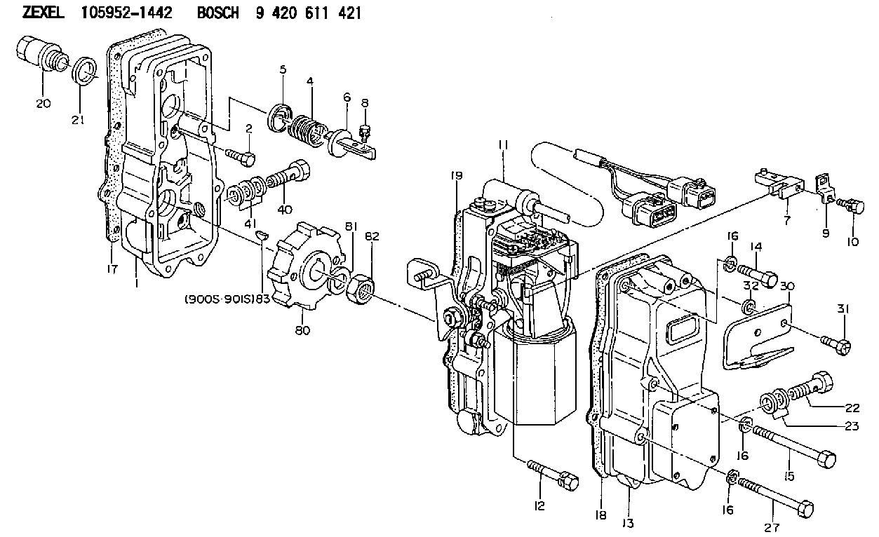
| 1. | [1] | 159560-2320 | GOVERNOR HOUSING |
| 2. | [8] | 139006-4100 | BLEEDER SCREW |
| 4. | [1] | 159564-0000 | COILED SPRING |
| 5. | [1] | 159564-4000 | SLOTTED WASHER |
| 6. | [1] | 159564-4100 | SLOTTED WASHER |
| 7. | [1] | 159564-7321 | CONNECTOR |
| 8. | [1] | 020105-1240 | BLEEDER SCREW M5P0.8L12 |
| 9. | [1] | 159564-0501 | PLATE |
| 9B. | [1] | 159564-6500 | PLATE |
| 9C. | [1] | 159584-5200 | PLATE |
| 10. | [1] | 020105-1240 | BLEEDER SCREW M5P0.8L12 |
| 11. | [1] | 159569-2221 | ACTUATOR |
| 12. | [2] | 020106-4040 | BLEEDER SCREW |
| 13. | [1] | 159561-0400 | GOVERNOR COVER |
| 14. | [4] | 010006-7040 | BLEEDER SCREW M6P1L70 |
| 15. | [2] | 029010-6550 | BLEEDER SCREW |
| 16. | [8] | 014110-6440 | LOCKING WASHER |
| 16. | [8] | 014110-6440 | LOCKING WASHER |
| 16. | [8] | 014110-6440 | LOCKING WASHER |
| 17. | [1] | 159566-4700 | GASKET |
| 18. | [1] | 154390-0400 | GASKET |
| 19. | [1] | 154390-0500 | GASKET |
| 20. | [1] | 153021-5000 | CAP |
| 21. | [1] | 026524-3040 | GASKET |
| 22. | [1] | 159564-0800 | EYE BOLT |
| 23. | [2] | 139514-0000 | GASKET D19.2&14.2T1.0 |
| 27. | [2] | 139006-1300 | BLEEDER SCREW M6P1L76 |
| 30. | [1] | 159584-2221 | BRACKET |
| 31. | [2] | 020106-1840 | BLEEDER SCREW M6P1L18 |
| 32. | [2] | 154370-9400 | PLAIN WASHER |
| 40. | [1] | 139812-3020 | EYE BOLT |
| 41. | [3] | 139512-0000 | GASKET D17.2&12.2T1.0 |
| 80. | [1] | 159584-0000 | TOOTHED GEAR |
| 81. | [1] | 014111-2420 | LOCKING WASHER |
| 82. | [1] | 013031-2120 | UNION NUT |
| 83. | [1] | 025803-1310 | WOODRUFF KEY |
| 900S. | [1] | 025803-1310 | WOODRUFF KEY |
| 901S. | [1] | 025803-1610 | WOODRUFF KEY |
Include in #1:
106871-1112
as GOVERNOR
Cross reference number
Zexel num
Bosch num
Firm num
Name
Information:
Piston Pin Bearing Removal And Installation (Connecting rods that have straight sides on the piston pin end).
The 5P8639 Press Group and the 5P8655 Tool Group are used to remove and install the piston pin bearings in the connecting rods. Use the procedure that follows to remove and install the piston pin bearing from the connecting rod.Remove the crankshaft bearing from the large end of the connecting rod and install the cap on the rod.Put the connecting rod in an oven and get the temperature of the rod to 400°F (204°C).Put the 5P8654 Spacer in the counterbore of the base plate. Be sure the spacer is in the bore straight and is against the bottom of the counterbore. Put the
The 5P8639 Press Group and the 5P8655 Tool Group are used to remove and install the piston pin bearings in the connecting rods. Use the procedure that follows to remove and install the piston pin bearing from the connecting rod.Remove the crankshaft bearing from the large end of the connecting rod and install the cap on the rod.Put the connecting rod in an oven and get the temperature of the rod to 400°F (204°C).Put the 5P8654 Spacer in the counterbore of the base plate. Be sure the spacer is in the bore straight and is against the bottom of the counterbore. Put the