Information actuator
BOSCH
9 420 614 161
9420614161
ZEXEL
105952-0383
1059520383
Rating:
Scheme ###:
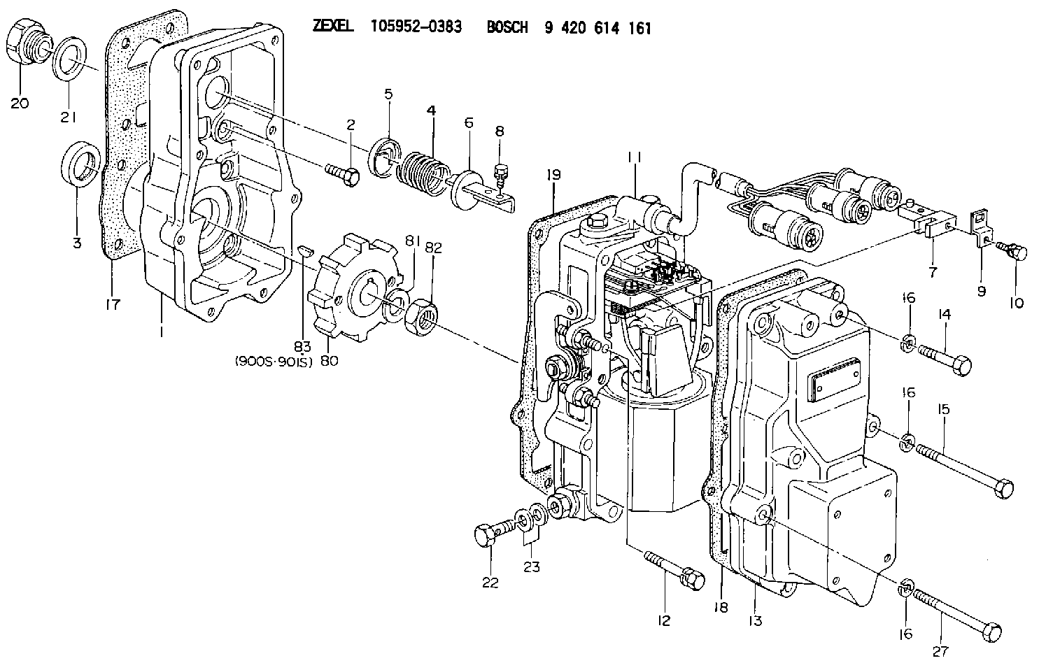
| 1. | [1] | 159560-0100 | GOVERNOR HOUSING |
| 2. | [8] | 139006-4100 | BLEEDER SCREW |
| 3. | [1] | 029621-7050 | PACKING RING |
| 4. | [1] | 159564-0000 | COILED SPRING |
| 5. | [1] | 159564-4000 | SLOTTED WASHER |
| 6. | [1] | 159564-4100 | SLOTTED WASHER |
| 7. | [1] | 159564-7321 | CONNECTOR |
| 8. | [1] | 020105-1240 | BLEEDER SCREW M5P0.8L12 |
| 9. | [1] | 159564-0501 | PLATE |
| 9B. | [1] | 159564-6500 | PLATE |
| 9C. | [1] | 159584-5200 | PLATE |
| 10. | [1] | 020105-1240 | BLEEDER SCREW M5P0.8L12 |
| 11. | [1] | 159567-5822 | ACTUATOR |
| 12. | [2] | 020106-4040 | BLEEDER SCREW |
| 13. | [1] | 159561-0400 | GOVERNOR COVER |
| 14. | [4] | 010006-7040 | BLEEDER SCREW M6P1L70 |
| 15. | [2] | 010006-5540 | BLEEDER SCREW M6P1L55 4T |
| 16. | [8] | 014110-6440 | LOCKING WASHER |
| 16. | [8] | 014110-6440 | LOCKING WASHER |
| 16. | [8] | 014110-6440 | LOCKING WASHER |
| 17. | [1] | 154371-5600 | GASKET |
| 18. | [1] | 154390-0400 | GASKET |
| 19. | [1] | 154390-0500 | GASKET |
| 20. | [1] | 155404-1700 | CAP |
| 21. | [1] | 026524-3040 | GASKET |
| 22. | [1] | 029731-4680 | EYE BOLT |
| 23. | [2] | 029341-4130 | GASKET D20&13.8T2* |
| 27. | [2] | 139006-1300 | BLEEDER SCREW M6P1L76 |
| 80. | [1] | 159564-8600 | TOOTHED GEAR |
| 81. | [1] | 014111-2420 | LOCKING WASHER |
| 82. | [1] | 013031-2120 | UNION NUT |
| 83. | [1] | 025803-1310 | WOODRUFF KEY |
| 900S. | [1] | 025803-1310 | WOODRUFF KEY |
| 901S. | [1] | 025803-1610 | WOODRUFF KEY |
Include in #1:
106672-9613
as GOVERNOR
Cross reference number
Zexel num
Bosch num
Firm num
Name
Information:
Problem
The retainer clips for the fuel injectors may crack or break on certain Challenger 75 Tractors. Also, the unit injector rocker arms may crack.
Affected Product
Mode & Identification Number
CH75 (4CJ1-308, 4CJ311-317, 4CJ320-331, 4CJ350, 4CJ356,4CJ375-378, 4CJ380, 4CJ382, 4CJ383, 4CJ386, 4CJ391, 4CJ394, 4CJ396, 4CJ406)
Parts Needed
6 - 7E8872 Rocker Arm Assembly (Use as needed)6 - 6I2538 Clip6 - 0R3398 Injector Group (Use as needed)Action Required
See attached rework procedure.
Service Claim Allowances
If required, add the following:
0.5 Hr R&I first fuel injector0.4 Hr R&I each additional fuel injectorParts Disposition
Handle the parts in accordance with your Warranty Bulletin on warranty parts handling.
Attach.
(1-Rework Procedure)Rework Procedure
1. Check for 3X stamped on the block next to the serial number plate. If the block has been stamped do not proceed with the rework unless suspect injectors have recently been installed in that engine. Check SIMS history to be sure.2. Remove hood from over engine, valve covers, and rocker arm stands.3. Inspect the injector rocker arms for the heat code and die code as shown in Illustration 1. Replace any injector rocker arms that have both heat code "1" and die code "1*C" (* Note symbol in Illustration.)
Illustration 1 - Injector Rocker Arm Identification Injector rocker arms must have BOTH heat code "1" and die code "1*C" to be eligible for replacement.
4. Inspect unit injectors for a paint strip across the top face of the spring retainer (either yellow or red). A paint stripe indicates the unit injector has been reworked previously.5. Remove the return to tank fuel line at the fuel manifold adapter (siphon break) and install a 0-100 psi gauge at the manifold.6. Use an O-ring pick to remove the O-ring from the spring retainer of each injector to be reworked. Remove the rocker arm thrust pad from each injector.7. Pressurize fuel system using the priming pump to 30 psi and maintain pressure from 15-30 psi during rework (fuel pressure keeps the injector plunger extended during clip replacement).8. Inspect the 9U5300 Unit Injector Spring Compressor Group. See Illustration 2. The 9U5320 Fixture is for off engine use only.
Illustration 2 - 9U5300 Unit Injector Spring Compressor GroupInstall the compressor group into a rocker arm support bolt hole with the arm aligned over a unit injector spring. Be sure the 5P0541 Nut is backed off to the top of the 9U5321 Tube before tightening the 7X0909 Bolt.
Install the compressor at hole locations closest to the inlet valves.Tighten the 5P0541 Nut to compress the injector spring only enough to allow removal of the clip (the clip is like a valve keeper).
9. Use a small magnet (pencil size works best) and a suitable clip removal tool to remove the old clip from the injector. Do not release tension on the spring until a new clip is installed. Releasing tension before a new clip is installed will cause the injector will come apart. See Illustration 3.
Illustration 3 - Use caution when handling injectors with missing clips. Loose springs and retainers will allow ball to come loose and fall into the engine.10. Inspect the clip